Chapter 4 - Operation Examples
4-10
Operation
example (2)
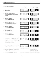
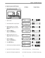
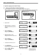
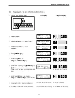
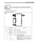
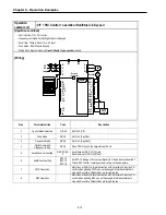
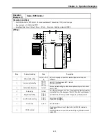
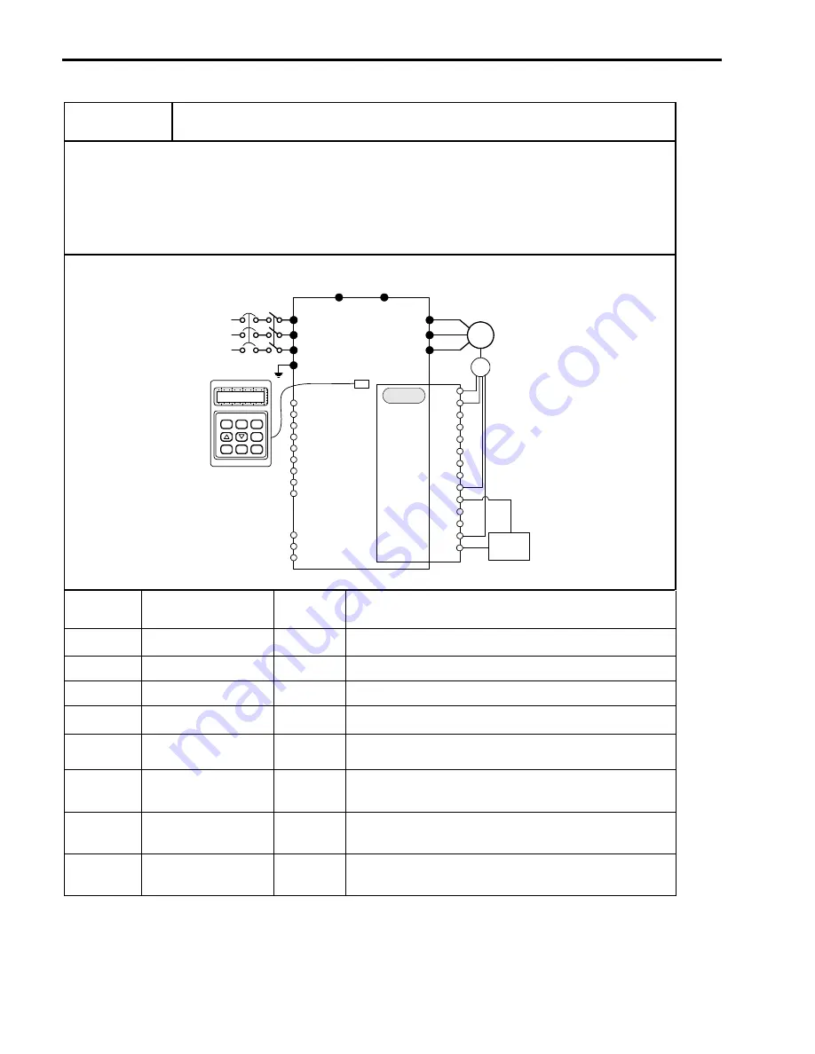
(V/F + PG) C operation (Run/Stop) via Keypad
[Operation condition]
-. Control mode: V/F + PG control
-. Frequency command: 50[Hz] Digital input via Keypad
-. Accel time : 15[sec], Decel time : 25 [sec]
-. Drive mode : Run/Stop via Keypad
-. Wiring block diagram when an
Open Collector- type encoder
is used.
[Wiring]
AOC
R
S
T
G
U
V
W
B1
B2
FX
RX
BX
RST
JOG
P1
P2
P3
CM
VR
V1
5G
IM
3P
AC
Input
BOC
A+
A-
B+
B-
FBA
FBB
GND
E
Encoder
GND
+5V
+5V
VCC
VCC
Keypad
connector
MODE
PROG
ENT
REV
SHIFT
ESC
STOP
RESET
FWD
LC-200
Sub-B
Power
Supply
12V-15V DC
Step
Parameter setting
Code
Description
1
Control Mode Selection
FU2-39
Set it to 0 {V/F}.
2
Drive mode
DRV-3
Set it to 0 {KeyPad}.
3
Frequency Mode
DRV-4
Set it to 0
{
KeyPad-1}.
4
Digital Command
Frequency setting
DRV-0
Press PROG key on the keypad to set 50 Hz
5
Accel/Decel time setting
DRV-2 DRV-
3
Accel time: set DRV-2 to 15[sec]
Decel time: set DRV-3 to 25[sec]
6
Sub-B board setting
EXT-12
EXT-15
EXT-16
Set EXT-12 [Usage of Pulse Input Signal] to 1 {Feed-back} and set EXT-
15 and EXT-16 after checking encoder rating on the nameplate.
7 FWD
Operation
Motor runs at 50[Hz] in forward direction with Accel time 15[sec] by PG
control when pressing FWD key on the keypad. Motor decelerates to
stop with Decel time 25[sec] when pressing Stop key.
8 REV
Operation
Motor runs at 50[Hz] in reverse direction with Accel time 15[sec] by PG
control when pressing REV key on the keypad. Motor decelerates to
stop with Decel time 25[sec] when pressing Stop key.
Summary of Contents for 30 HP30
Page 6: ......
Page 12: ......
Page 16: ...Chapter 1 Installation 1 4 BLANK ...
Page 18: ...Chapter 1 Installation 1 6 BLANK ...
Page 28: ...Chapter 1 Installation 1 16 Notes ...
Page 39: ...Chapter 2 Operation 2 11 Notes ...
Page 40: ......
Page 46: ......
Page 60: ...Chapter 4 Operation Examples 4 14 Notes ...
Page 83: ...Chapter 5 Parameter List 5 23 Notes ...
Page 84: ......
Page 92: ...Chapter 6 Parameter Description DRV 6 8 Notes ...
Page 105: ......
Page 106: ...Chapter 6 Parameter description FU1 6 14 Notes ...
Page 126: ...Chapter 6 Parameter Description FU2 6 34 Notes ...
Page 144: ...Chapter 6 Parameter Description I O 6 52 Notes ...
Page 162: ......
Page 188: ...Chapter 7 Options 7 26 Type 1 Max 400 Watt Type 2 Max 600 Watt A ...
Page 189: ...Chapter 7 Options 7 27 Type 3 ...
Page 194: ......
Page 204: ......
Page 210: ......

