Chapter 6 - Parameter description [FU1]
6-15
☞
Note:
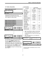
When FU2-40 [Control Mode] is set to ‘Sensorless’,
the torque boost value is the rate per thousand of inverter
rated voltage.
[Auto Torque Boost]:
Inverter outputs high starting torque
by automatic boosting according to the load.
☞
Note:
Auto torque boost is only available for the 1
st
motor.
Manual torque boost must be used for the 2
nd
motor.
☞
Note:
The auto torque boost value is added to the manual
torque boost value.
☞
Note:
Auto torque boost is available only when FU2-40
[Control Mode] is set to ‘V/F’.
☞
Note:
Conduct Auto tuning in FU2-41 [Auto tuning] to use
Auto torque boost effectively.
[Constant Torque Loads: Conveyor, Moving Equip. etc.]
[Ascending and Descending Loads: Parking, Hoist etc.]
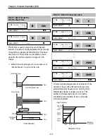
FU1-29: Volts/Hz Pattern
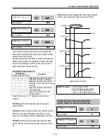
This is the pattern of voltage/frequency ratio. Select the
proper V/F pattern according to the load. The motor torque
is dependent on this V/F pattern.
[Linear]
pattern is used where constant torque is required.
This pattern maintains a linear volts/frequency ratio from
zero to base frequency. This pattern is appropriate for
constant torque applications.
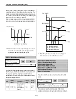
[Square]
pattern is used where variable torque is required.
This pattern maintains squared volts/hertz ratio. This
pattern is appropriate for fans, pumps, etc.
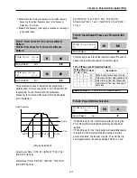
[User V/F]
pattern is used for special applications. Users
can adjust the volts/frequency ratio according to the
application. This is accomplished by setting the voltage
and frequency, respectively, at four points between starting
frequency and base frequency. The four points of voltage
and frequency are set in FU1-30 through FU1-37.
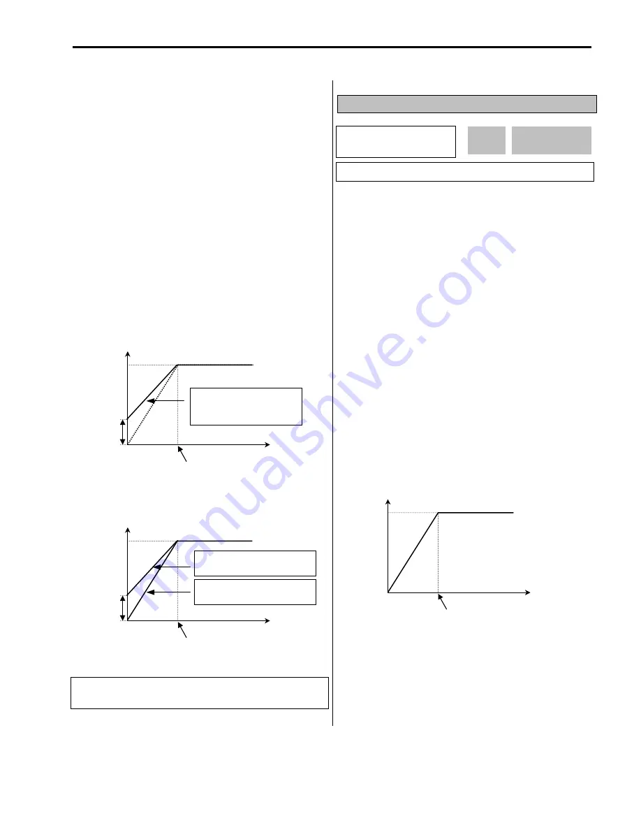
[V/F Pattern: ‘Linear’]
Output Voltage
Output
Frequency
Freq. Base
100%
Manual
Boost
Value
Forward and Reverse direction
(Set the same value for FU1-27
and FU1-28)
Output Voltage
Output
Frequency
FU1-21
100%
Manual
Boost
Value
Forward Direction - Motoring
(Set FU1-27 to a value)
Reverse Direction - Regenerating
(Set FU1-28 to ‘0’)
FU1
►
V/F pattern
29 Linear
0
29
Factory Default:
Linear
0
Related Functions:
FU1-29
[Volts/Hz
Pattern]
FU2-40 [Control Mode selection]
Output Voltage
Output
Frequency
Freq. Base
100%
Summary of Contents for 30 HP30
Page 6: ......
Page 12: ......
Page 16: ...Chapter 1 Installation 1 4 BLANK ...
Page 18: ...Chapter 1 Installation 1 6 BLANK ...
Page 28: ...Chapter 1 Installation 1 16 Notes ...
Page 39: ...Chapter 2 Operation 2 11 Notes ...
Page 40: ......
Page 46: ......
Page 60: ...Chapter 4 Operation Examples 4 14 Notes ...
Page 83: ...Chapter 5 Parameter List 5 23 Notes ...
Page 84: ......
Page 92: ...Chapter 6 Parameter Description DRV 6 8 Notes ...
Page 105: ......
Page 106: ...Chapter 6 Parameter description FU1 6 14 Notes ...
Page 126: ...Chapter 6 Parameter Description FU2 6 34 Notes ...
Page 144: ...Chapter 6 Parameter Description I O 6 52 Notes ...
Page 162: ......
Page 188: ...Chapter 7 Options 7 26 Type 1 Max 400 Watt Type 2 Max 600 Watt A ...
Page 189: ...Chapter 7 Options 7 27 Type 3 ...
Page 194: ......
Page 204: ......
Page 210: ......


