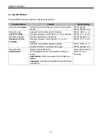
Chapter 4 – Function Settings
4-6
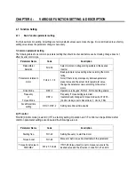
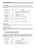
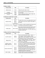
5) Parameter initialize
Parameter Name
Code
Description
Software version
FU2-79
Display the inverter software version
Parameter
Read/Write/Initialize/Write
protection
FU2-91
FU2-92
FU2-93
FU2-94
[FU2-91], [FU2-92]: Copying parameters from other
inverter enabled
[FU2-93]: Initializing parameters to factory setting values
[FU2-94] : Parameter write disabled
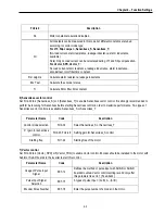
6) Protection & fault detection level setting
Parameter Name
Code
Description
Electronic thermal
FU1-50
FU1-51
FU1-52
FU1-53
Protection of the motor from overheating without the use of
external thermal relay. Refer to parameter descriptions for
more detail.
Overload alarm and trip
FU1-54, FU1-55
FU1-56, FU1-57
FU1-58
Warning alarm outputs and displays the trip message when
overcurrent above the threshold value keeps on.
Stall prevention
FU1-59, FU1-60
Set the output current level at which the output freq will be
adjusted to prevent the motor from stoping due to over-
current etc. it activates during accel/ constant speed/ decel
to prevent the motor stall.
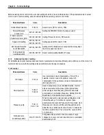
7) Starting / Accel/ Decel / Stopping pattern setting
Parameter Name
Code
Description
Accel/Decel pattern
FU1-05
FU1-06
5 types of Accel/ Decel pattern: ‘Linear’, ‘S-curve’, ’U-
curve’, ’Minimum’, ‘Optimum’ settable according to
appplication and load characteristic. If ‘S-curve’ is selected,
the desired value of [FU2-17], [FU2-18] is settable.
Stopping method
FU1-07
3 types of stopping method ‘Decel’, ‘DC-brake’, ‘Free-run’
selectable. If ‘DC-brake’ is selected, the desired value of
[FU1-8]~ [FU1-11] is settable.
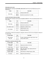
Starting DC Injection
Braking Voltage/ Time
FU1-12
FU1-13
The motor accelerates after the preset [FU1-12] for the
preset [FU1-13] is applied. Starting DC injection braking is
inactive when the value is set to 0 in control mode other
than V/F and Slip compensation.
Frequency Limit selection
FU1-23
Fu1-24
FU1-25
Limits the active frequency. Inverter operates at the freq
range between upper freq limit [FU1-25] and bottom freq
limit [FU1-24] and higher/ lower freq value is entered, it is
automatically replaced by limit value. Setting range: [FU1-
20] Maximum freq to [FU1-21] Base freq.
Dynamic braking
FU2-75
FU2-76
Select the DB resistor mode when the regenerative load. Is
connected. Refer to DBU manual for more details.
Summary of Contents for 30 HP30
Page 6: ......
Page 12: ......
Page 16: ...Chapter 1 Installation 1 4 BLANK ...
Page 18: ...Chapter 1 Installation 1 6 BLANK ...
Page 28: ...Chapter 1 Installation 1 16 Notes ...
Page 39: ...Chapter 2 Operation 2 11 Notes ...
Page 40: ......
Page 46: ......
Page 60: ...Chapter 4 Operation Examples 4 14 Notes ...
Page 83: ...Chapter 5 Parameter List 5 23 Notes ...
Page 84: ......
Page 92: ...Chapter 6 Parameter Description DRV 6 8 Notes ...
Page 105: ......
Page 106: ...Chapter 6 Parameter description FU1 6 14 Notes ...
Page 126: ...Chapter 6 Parameter Description FU2 6 34 Notes ...
Page 144: ...Chapter 6 Parameter Description I O 6 52 Notes ...
Page 162: ......
Page 188: ...Chapter 7 Options 7 26 Type 1 Max 400 Watt Type 2 Max 600 Watt A ...
Page 189: ...Chapter 7 Options 7 27 Type 3 ...
Page 194: ......
Page 204: ......
Page 210: ......

