


Operate the switches with dry hands.
Otherwise, you may get an electric shock.
Do not use the cable when its insulating tube is damaged.
Otherwise, you may get an electric shock.
Do not subject the cables to scratches, excessive stress, heavy loads or pinching.
Otherwise, you may get an electric shock.
CAUTION
Install the inverter on a non-flammable surface. Do not place flammable material nearby.
Otherwise, fire could occur.
Disconnect the input power if the inverter gets damaged.
Otherwise, it could result in a secondary accident and fire.
After the input power is applied or removed, the inverter will remain hot for a couple of
minutes.
Otherwise, you may get bodily injuries such as skin-burn or damage.
Do not apply power to a damaged inverter or to an inverter with parts missing even if the
installation is complete.
Otherwise, electric shock could occur.
Do not allow lint, paper, wood chips, dust, metallic chips or other foreign matter into the
drive.
Otherwise,
fire or accident
could occur.
OPERATING PRECAUTIONS
(1)
Handling and installation
Handle according to the weight of the product.
Do not stack the inverter boxes higher than the number recommended.
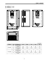
Install according to instructions specified in this manual.
Do not open the cover during delivery.
Do not place heavy items on the inverter.
Check the inverter mounting orientation is correct.
Do not drop the inverter, or subject it to impact.
Verify that the inverter is solidly grounded. Use ground impedance of 100ohm or less for 200 V Class and
10ohm or less for 400V class.
Take protective measures against ESD (Electrostatic Discharge) before touching the pcb for inspection or
installation.
Summary of Contents for 30 HP30
Page 6: ......
Page 12: ......
Page 16: ...Chapter 1 Installation 1 4 BLANK ...
Page 18: ...Chapter 1 Installation 1 6 BLANK ...
Page 28: ...Chapter 1 Installation 1 16 Notes ...
Page 39: ...Chapter 2 Operation 2 11 Notes ...
Page 40: ......
Page 46: ......
Page 60: ...Chapter 4 Operation Examples 4 14 Notes ...
Page 83: ...Chapter 5 Parameter List 5 23 Notes ...
Page 84: ......
Page 92: ...Chapter 6 Parameter Description DRV 6 8 Notes ...
Page 105: ......
Page 106: ...Chapter 6 Parameter description FU1 6 14 Notes ...
Page 126: ...Chapter 6 Parameter Description FU2 6 34 Notes ...
Page 144: ...Chapter 6 Parameter Description I O 6 52 Notes ...
Page 162: ......
Page 188: ...Chapter 7 Options 7 26 Type 1 Max 400 Watt Type 2 Max 600 Watt A ...
Page 189: ...Chapter 7 Options 7 27 Type 3 ...
Page 194: ......
Page 204: ......
Page 210: ......


