Chapter 6 - Parameter Description [I/O]
6-42
[Trv Off.Lo]
This function is used to make negative offset during
traverse operation.
[Trv Off.Hi]
This function is used to make positive offset during
traverse operation.
[Interlock1, 2, 3, 4]
This function is used for MMC operation. Refer to MMC
operation.
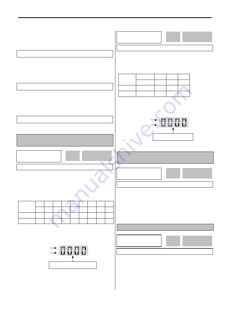
I/O-15: Terminal Input Status
I/O-16: Terminal Output Status
This code displays the input status of control terminals.
Terminals P4, P5, P6 and Q1, Q2, Q3 are provided on
optional Sub-Board.
[LCD Keypad Display]
JOG FX RX P6 P5 P4 P3 P2 P1
Input
Terminals Bit 8 Bit 7 Bit 6 Bit 5 Bit 4 Bit 3 Bit 2 Bit 1 Bit 0
OFF
status
0 0 0 0 0 0 0 0 0
ON
status 1 1 1 1 1 1 1 1 1
[7-Segment Keypad Display]
The ‘JOG’ terminal is not displayed on 7-Segment keypad.
This code displays the output status of control terminals.
[LCD Keypad Display]
AXA-AXC Q3 Q2 Q1
Output
Terminals
Bit 3
Bit 2 Bit 1 Bit 0
OFF
status
0 0 0 0
ON
status
1 1 1 1
[7-Segment Keypad Display]
The ‘JOG’ terminal is not displayed on 7-Segment keypad.
I/O-17: Filtering Time Constant for Multi-function
Input Terminals
This is the response time constant for terminal inputs (JOG,
FX, RX, P3, P2, P1, RST, BX). This is useful where there
is a potential for noise. The response time is determined
by ‘Filtering time constant * 0.5msec’.
I/O-20: Jog Frequency
This code sets the jog frequency. See [Speed-L, Speed-M,
Speed-H] in I/O-12 ~ I/O-14.
I/O
►
In status
15 000000000
0000
15
Factory Default:
000000000
OFF status
ON status
FX RX P6 P5 P4 P3 P2 P1
I/O
►
Out status
16 0000
0000
16
Factory Default:
0000
OFF status
ON status
AXA-AXC Q3 Q2 Q1
I/O
►
Ti Filt Num
17 15
15
17
Factory Default:
15
15
I/O
►
Jog freq
20 10.00 Hz
10.00
20
Factory Default:
10.00 Hz
10.00
Related Functions:
APP-06 ~ APP-07 [Traverse Offset]
Related Functions:
APP-06 ~ APP-07 [Traverse Offset]
Related Functions:
APP-29 [Inter-Lock Selection]
Summary of Contents for 30 HP30
Page 6: ......
Page 12: ......
Page 16: ...Chapter 1 Installation 1 4 BLANK ...
Page 18: ...Chapter 1 Installation 1 6 BLANK ...
Page 28: ...Chapter 1 Installation 1 16 Notes ...
Page 39: ...Chapter 2 Operation 2 11 Notes ...
Page 40: ......
Page 46: ......
Page 60: ...Chapter 4 Operation Examples 4 14 Notes ...
Page 83: ...Chapter 5 Parameter List 5 23 Notes ...
Page 84: ......
Page 92: ...Chapter 6 Parameter Description DRV 6 8 Notes ...
Page 105: ......
Page 106: ...Chapter 6 Parameter description FU1 6 14 Notes ...
Page 126: ...Chapter 6 Parameter Description FU2 6 34 Notes ...
Page 144: ...Chapter 6 Parameter Description I O 6 52 Notes ...
Page 162: ......
Page 188: ...Chapter 7 Options 7 26 Type 1 Max 400 Watt Type 2 Max 600 Watt A ...
Page 189: ...Chapter 7 Options 7 27 Type 3 ...
Page 194: ......
Page 204: ......
Page 210: ......


