8-1
CHAPTER 8 -
TROUBLESHOOTING & MAINTENANCE
8.1 Fault Display
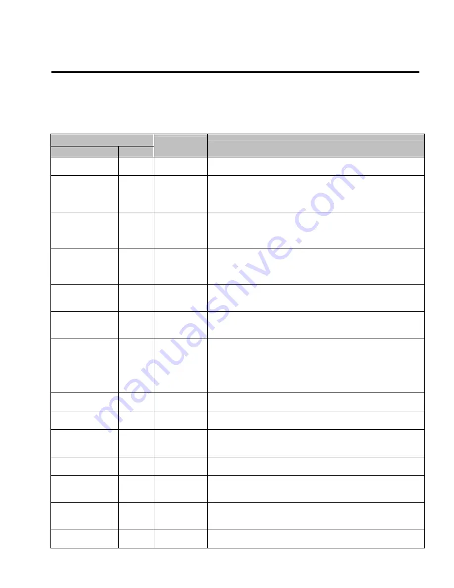
When a fault occurs, the inverter turns off its output and displays the fault status in DRV-07. The last 5 faults are saved in
FU2-01 through FU2-05 with the operation status at the instance of fault.
Keypad Display
LCD
7-Segment
Protective
Function
Description
Over Current 1
OC1
Over Current
Protection
The inverter turns off its output when the output current of the inverter flows
more than 200% of the inverter rated current.
Ground Fault
GF
Ground Fault
Protection
The inverter turns off its output when a ground fault occurs and the ground fault
current is more than the internal setting value of the inverter. Over current trip
function may protect the inverter when a ground fault occurs due to a low
ground fault resistance.
Over Voltage
OV
Over voltage
protection
The inverter turns off its output if the DC voltage of the main circuit increases
higher than the rated value when the motor decelerates or when regenerative
energy flows back to the inverter due to a regenerative load. This fault can also
occur due to a surge voltage generated at the power supply system.
Over Load
OLT
Current Limit
Protection
(Overload
Protection)
The inverter turns off its output if the output current of the inverter flows at
180% of the inverter rated current for more than the current limit time (S/W).
Fuse Open
FUSE
Fuse Open
The inverter turns off its output by opening the fuse when something is wrong
with the main circuit IGBT to protect the wiring from being damaged from short
currents.
Over Heat
OH
Heat Sink
Over Heat
The inverter turns off its output if the heat sink over heats due to a damaged
cooling fan or an alien substance in the cooling fan by detecting the
temperature of the heat sink.
E-Thermal ETH
Electronic
Thermal
The internal electronic thermal of the inverter determines the over heating of the
motor. If the motor is overloaded the inverter turns off the output. The inverter
cannot protect the motor when driving a multi-pole motor or when driving
multiple motors, so consider thermal relays or other thermal protective devices
for each motor.
Overload capacity: 150% for 1 min
Ext Trip-A
EXTA
External fault A
Use this function if the user needs to turn off the output by an external fault
signal. (Normal Open Contact)
Ext Trip-B
EXTB
External fault B
Use this function if the user needs to turn off the output by an external fault
signal. (Normal Close Contact)
Low Voltage
LV
Low Voltage
Protection
The inverter turns off its output if the DC voltage is below the detection level
because insufficient torque or over heating of the motor can occurs when the
input voltage of the inverter drops.
Over Current 2
OC2
IGBT Short
The inverter turns off the output if an IGBT short through or an output short
occurs.
Out Phase Open
OPO
Output Phase
open
The inverter turns off its output when the one or more of the output (U, V, W)
phase is open. The inverter detects the output current to check the phase open
of the output.
BX BX
BX Protection
(Instant Cut Off)
Used for the emergency stop of the inverter. The inverter instantly turns off the
output when the BX terminal is turned ON, and returns to regular operation
when the BX terminal is turned OFF. Take caution when using this function.
Over Speed
OSPD
Overspeed
Protection
Inverter turns off its output when the motor runs in excess of Max. speed +
20Hz.
Summary of Contents for 30 HP30
Page 6: ......
Page 12: ......
Page 16: ...Chapter 1 Installation 1 4 BLANK ...
Page 18: ...Chapter 1 Installation 1 6 BLANK ...
Page 28: ...Chapter 1 Installation 1 16 Notes ...
Page 39: ...Chapter 2 Operation 2 11 Notes ...
Page 40: ......
Page 46: ......
Page 60: ...Chapter 4 Operation Examples 4 14 Notes ...
Page 83: ...Chapter 5 Parameter List 5 23 Notes ...
Page 84: ......
Page 92: ...Chapter 6 Parameter Description DRV 6 8 Notes ...
Page 105: ......
Page 106: ...Chapter 6 Parameter description FU1 6 14 Notes ...
Page 126: ...Chapter 6 Parameter Description FU2 6 34 Notes ...
Page 144: ...Chapter 6 Parameter Description I O 6 52 Notes ...
Page 162: ......
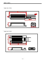
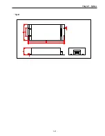
Page 188: ...Chapter 7 Options 7 26 Type 1 Max 400 Watt Type 2 Max 600 Watt A ...
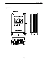
Page 189: ...Chapter 7 Options 7 27 Type 3 ...
Page 194: ......
Page 204: ......
Page 210: ......

