


Chapter 7 - Options
7-4
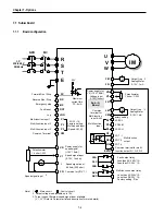
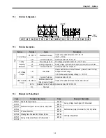
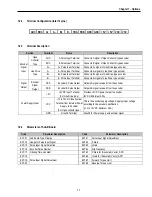
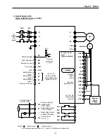
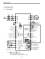
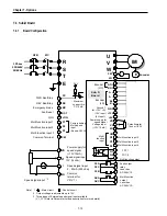
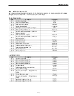
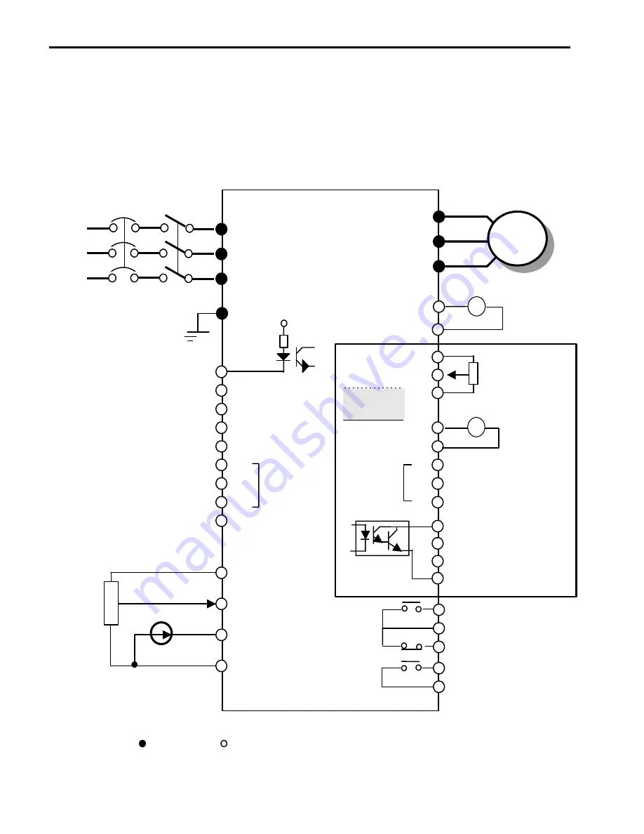
7.1 Sub-A board
7.1.1 Board
configuration
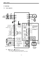
3 P
230/460 V
50/60 Hz
IM
U
V
W
E
R
S
T
+
FM
5G
30A
30B
30C
AXA
AXC
Multi-function output relay
VR
V1
I
5G
(0-10V, 1 kohm)
Common for VR,V1,I
3. Three types of External speed signal input available.
(V, I, V+I, Refer to Parameter list and description for more details)
NFB
MC
24 V
CM
LM
P4
P5
P6
Q1
Q2
Q3
EXTG
VR
V2
5G
XCEL-L
Multi-function
input
Common
terminal for
Multi-function
input & LM
Common terminal for multi-
function output Q1, Q2, Q3
FDT - 1
FDT - 2
FDT - 3
+
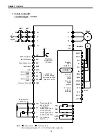
Sub - A
Board
F
M
L
M
XCEL-M
XCEL-H
Factory setting
Common Terminal
Forward Run / Stop
Emergency stop
Fault reset
Jog
Multi-function input 1
Multi-function input 2
Multi-function input 3
FX
RX
BX
RST
JOG
P2
P3
P1
CM
Output freq
*2
Analog Meter
0-10V, 1mA
*2
Output freq
Analog Meter
Potentiometer
1 kohm, 1/2W
Fault output relay
Less than AC 250V,1A
Less than DC 30V, 1A
Less than AC 250V,1A
Less than DC 30V, 1A
Factory setting: 'Run'
Power supply for
speed signal
(+12V 10mA)
Speed signal input
4-20mA (250 ohm)
Speed signal input
Speed signal input
*3
Note)
1.
: Main circuit
: Control circuit
2. Output voltage is adjustable up to 12V.
.
I/O-12~14:
Factory setting:
Multi-speed input
(Speed-L,M,H)
Reverse Run / Stop
1 k ohm,1/2W
Potentiometer
Power supply for
V2 (+12V 10mA)
Voltage input
0-10V(1kohm)
Multi-function
output
Maximum
current thru
PC: 5mA
0-10V, 1mA
Summary of Contents for 30 HP30
Page 6: ......
Page 12: ......
Page 16: ...Chapter 1 Installation 1 4 BLANK ...
Page 18: ...Chapter 1 Installation 1 6 BLANK ...
Page 28: ...Chapter 1 Installation 1 16 Notes ...
Page 39: ...Chapter 2 Operation 2 11 Notes ...
Page 40: ......
Page 46: ......
Page 60: ...Chapter 4 Operation Examples 4 14 Notes ...
Page 83: ...Chapter 5 Parameter List 5 23 Notes ...
Page 84: ......
Page 92: ...Chapter 6 Parameter Description DRV 6 8 Notes ...
Page 105: ......
Page 106: ...Chapter 6 Parameter description FU1 6 14 Notes ...
Page 126: ...Chapter 6 Parameter Description FU2 6 34 Notes ...
Page 144: ...Chapter 6 Parameter Description I O 6 52 Notes ...
Page 162: ......
Page 188: ...Chapter 7 Options 7 26 Type 1 Max 400 Watt Type 2 Max 600 Watt A ...
Page 189: ...Chapter 7 Options 7 27 Type 3 ...
Page 194: ......
Page 204: ......
Page 210: ......


