Chapter 6 - Parameter Description [EXT]
6-61
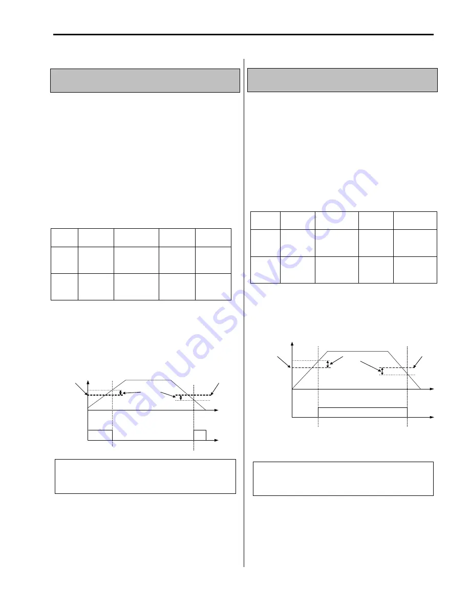
EXT-54: Zero Speed Detection Level
EXT-55: Zero Speed Detection Bandwidth
Used to set the zero speed detection (SUB-B)
Only valid when FU2-39 [Control mode selection] is
set to Vector_SPD, Vector_TRQ.
Detect the zero speed using I/O-44 [Multi-function
auxiliary contact output selection]. Set Zspd Dect in
I/O-44 [Multi-function auxiliary contact output] to
activate this function.
➨
Note : Sub-board is needed to use multi-function output
terminal Q1,Q2,Q3.
Code
Keypad
Display
Parameter
Name
Factory
setting
Setting
range
EXT-
54
ZSD
Level
Zero Speed
Detection
Level
0.3[Hz]
0 – 120
[Hz]
EXT-
55
ZSD
Band
Zero Speed
Detection
Bandwidth
0.1[Hz]
0 – 0.3
[Hz]
Auxiliary contact relay activates as shown below if the
following settings are applied to EXT-54 [Zero Speed
Detection Level] and EXT-55 [Zero Speed Detection
Bandwidth].
SPEED
AXA-
AXC
Close
EXT-54
ZSD
Level
EXT-55
ZSD
Band
EXT-54
ZSD
Level
Close
EXT-56: Torque Detection Level
EXT-57: Torque Detection Bandwidth
Use to set output torque detection (SUB-B)
Only valid when FU2-39 [Control mode selection] is
set to Vector_SPD, Vector_TRQ.
Detect Torque using I/O-44 [Multi-function auxiliary
contact output selection].
➨
Note : Sub-board should be mounted to use multi-
function output terminal Q1,Q2,Q3.
EXT-56 [Torque Detection Level] and EXT-57 [Torque
Detection Bandwidth] are activated in the following
conditions as shown below.
TORQUE
AXA-
AXC
EXT-56
TD Level
EXT-57
TD Band/
2
EXT-56
TD Level
Close
Code
Keypad
Display
Description Factory
setting
Setting
range
EXT-56 TD
Level
Torque
Detection
Level
100[%]
0 – 150 [%]
EXT-57 TD
Band
Torque
Detection
Bandwidth
5[%]
0 – 10 [%]
Related parameters
: FU2-39 [Control mode selection]
I/O-44 [Multi-function auxiliary
contact output]
Related parameters
: FU2-39 [Control mode select]
I/O-44 [Multi-function auxiliary
contact output selection]
Summary of Contents for 30 HP30
Page 6: ......
Page 12: ......
Page 16: ...Chapter 1 Installation 1 4 BLANK ...
Page 18: ...Chapter 1 Installation 1 6 BLANK ...
Page 28: ...Chapter 1 Installation 1 16 Notes ...
Page 39: ...Chapter 2 Operation 2 11 Notes ...
Page 40: ......
Page 46: ......
Page 60: ...Chapter 4 Operation Examples 4 14 Notes ...
Page 83: ...Chapter 5 Parameter List 5 23 Notes ...
Page 84: ......
Page 92: ...Chapter 6 Parameter Description DRV 6 8 Notes ...
Page 105: ......
Page 106: ...Chapter 6 Parameter description FU1 6 14 Notes ...
Page 126: ...Chapter 6 Parameter Description FU2 6 34 Notes ...
Page 144: ...Chapter 6 Parameter Description I O 6 52 Notes ...
Page 162: ......
Page 188: ...Chapter 7 Options 7 26 Type 1 Max 400 Watt Type 2 Max 600 Watt A ...
Page 189: ...Chapter 7 Options 7 27 Type 3 ...
Page 194: ......
Page 204: ......
Page 210: ......


