

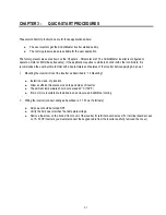

Chapter 3 - Quick-Start Procedures
3-4
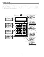
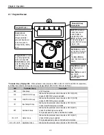
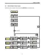
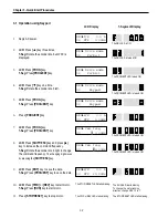
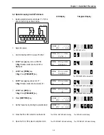
3.3 Operation using Keypad and Control Terminals
3.3.1
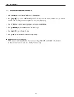
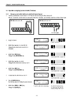
Frequency set by External Source and Run/Stop by Keypad
1.
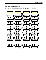
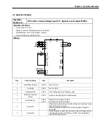
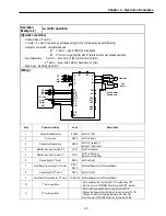
Install a potentiometer on terminals V1, VR, 5G and connect wiring as shown below left.
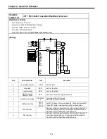
When a ‘4 to 20mA’ current source is used as the frequency reference, use terminals I and 5G as shown below right.
2.
Apply AC power.
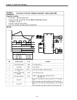
3.
LCD:
Press
[
▲
]
key to move DRV 03.
7-Seg:
Rotate encoder knob until ‘03’ is
displayed.
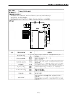
4.
LCD:
Press
[PROG]
key.
7-Seg:
Press
[PROG/ENT]
key.
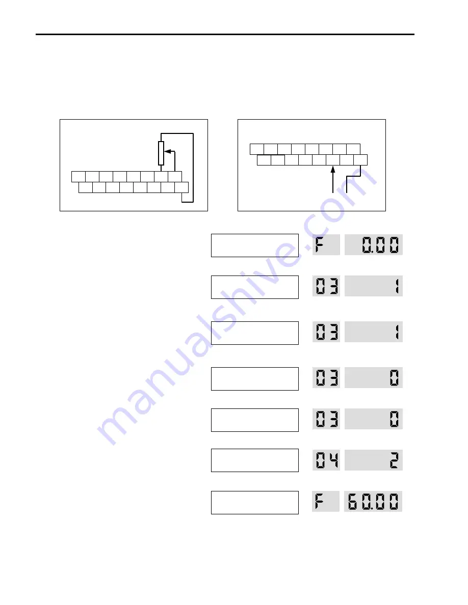
5.
LCD:
Press
[
▲
]
key one time.
7-Seg:
Rotate encoder knob and set at ‘0’.
6.
LCD:
Press
[ENT]
key.
7-Seg:
Press
[PROG/ENT]
key.
7.
Confirm that the DRV 04 is set at ‘V1’.
8.
Press
[SHIFT/ESC]
key.
Set the frequency by rotating the potentiometer.
9.
LCD:
Press
[FWD]
or
[REV]
key.
7-Seg:
Press
[RUN]
key.
P1 P2
JOG CM
P3 FX RX NC
CM BX
RST
I
VR VI
FM 5G
4 to 20mA signal
1
㏀
, 1/2 W
P1 P2
JOG
CM
P3 FX RX NC
CM BX
RST
I
VR VI
FM 5G
DRV 04
must be set at
V1
.
DRV 04
must be set at
I
.
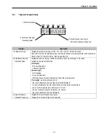
DRV
►
T/K 0.0 A
00 STP 0.00Hz
The DRV LED is ON.
DRV
►
Drive mode
03 Fx/Rx-1
DRV
►
Drive mode
03 Fx/Rx-1
The PROG/ENT LED is turned ON.
DRV
►
Drive mode
03 Keypad
The PROG/ENT LED is turned ON.
DRV
►
Drive mode
03 Keypad
The PROG/ENT LED is turned OFF.
DRV
►
Freq mode
04 V1
The PROG/ENT LED is turned ON.
DRV
►
T/V 0.0 A
00 STP 60.00Hz
The FWD or REV LED starts blinking.
The RUN LED starts blinking.
To change the motor running
direction, change DRV 13 to ‘1’.
Summary of Contents for 30 HP30
Page 6: ......
Page 12: ......
Page 16: ...Chapter 1 Installation 1 4 BLANK ...
Page 18: ...Chapter 1 Installation 1 6 BLANK ...
Page 28: ...Chapter 1 Installation 1 16 Notes ...
Page 39: ...Chapter 2 Operation 2 11 Notes ...
Page 40: ......
Page 46: ......
Page 60: ...Chapter 4 Operation Examples 4 14 Notes ...
Page 83: ...Chapter 5 Parameter List 5 23 Notes ...
Page 84: ......
Page 92: ...Chapter 6 Parameter Description DRV 6 8 Notes ...
Page 105: ......
Page 106: ...Chapter 6 Parameter description FU1 6 14 Notes ...
Page 126: ...Chapter 6 Parameter Description FU2 6 34 Notes ...
Page 144: ...Chapter 6 Parameter Description I O 6 52 Notes ...
Page 162: ......
Page 188: ...Chapter 7 Options 7 26 Type 1 Max 400 Watt Type 2 Max 600 Watt A ...
Page 189: ...Chapter 7 Options 7 27 Type 3 ...
Page 194: ......
Page 204: ......
Page 210: ......


