Chapter 6 - Parameter description [FU1]
6-13
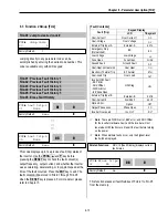
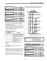
FU1-15: Hold Time
To set the time to maintain holding torque at zero speed
and stop the operation in a shortest time during
Vector_SPD mode operation
The inverter runs to maintain speed 0 for the hold
time in Vector_SPD mode and decelerates to stop
after the hold time elapse.
Operation method during Hold Time:
FU1-7[Stop mode] Decel: speed zero control
FU1-7[Stop mode] DC-brake
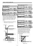
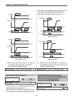
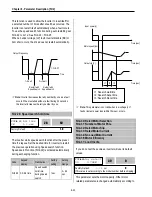
FU1-16: Pre-excitation Current
FU1-16 [Pre-excitation Current] is applied during FU1-14.
When the motor magnetic flux increases to match the
rated magnetic flux, pre-excitation current starts to
decrease. When the motor magnetic flux reaches to the
rated magnetic flux, the pre-excitation current matches the
rated pre-excitation current.
Code
LCD display
Factory setting
Setting range
FU1-16
Flux Force
100 [%]
100 ~ 500 [%]
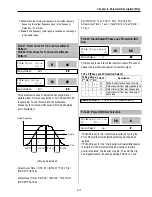
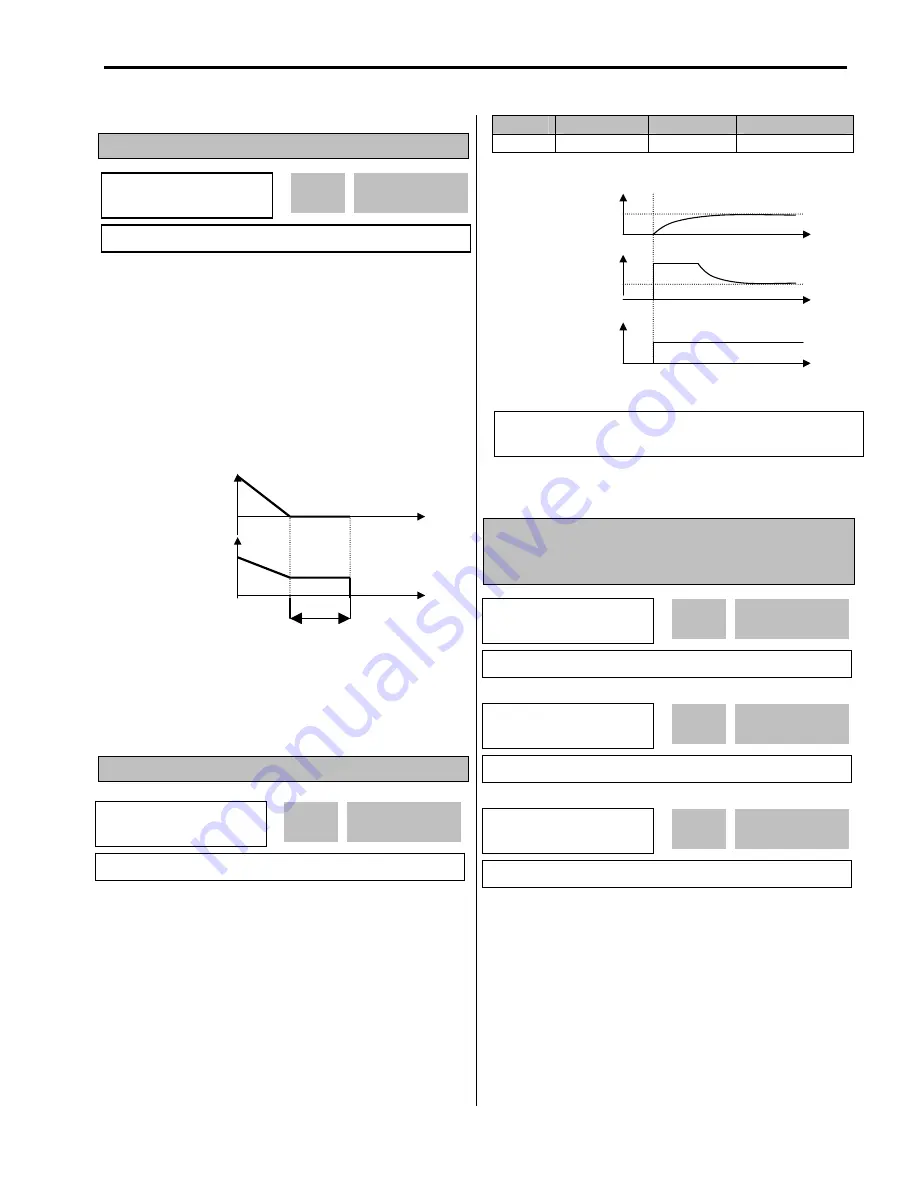
FU1-20: Maximum Frequency
FU1-21: Base Frequency
FU1-22: Starting Frequency
FU1-20 [Maximum Frequency] is the maximum output
frequency of the inverter. Make sure this maximum
frequency does not exceed the rated speed of the motor.
FU1-21 [Base Frequency] is the frequency where the
inverter outputs its rated voltage. In case of using a 50Hz
motor, set this to 50Hz.
FU1-22 [Starting Frequency] is the frequency where the
inverter starts to output its voltage.
Output
Voltage
[V]
Output Speed
[Hz or Rpm]
Hold time
FX-CM
Motor
magnetic flux
Excited current
FU1
►
Max freq
20 60.00 Hz
60.00
20
Factory Default:
60.00 Hz
60.00
FU1
►
Base freq
21 60.00 Hz
60.00
21
Factory Default:
60.00 Hz
60.00
FU1
►
Start freq
22 0.50 Hz
0.50
22
Factory Default:
0.50 Hz
0.50
FU1
►
Hold Time
15 1000 ms
1000
15
Factory Default:
1000 ms
1000
FU1
►
Flux Force
16 100.0 %
1 00.0
16
Factory Default:
100.0 %
100.0
Related Functions:
FU2-34 [No Load Motor Current (RMS)]
FU1-14 [Pre-excitation Time]
Summary of Contents for 30 HP30
Page 6: ......
Page 12: ......
Page 16: ...Chapter 1 Installation 1 4 BLANK ...
Page 18: ...Chapter 1 Installation 1 6 BLANK ...
Page 28: ...Chapter 1 Installation 1 16 Notes ...
Page 39: ...Chapter 2 Operation 2 11 Notes ...
Page 40: ......
Page 46: ......
Page 60: ...Chapter 4 Operation Examples 4 14 Notes ...
Page 83: ...Chapter 5 Parameter List 5 23 Notes ...
Page 84: ......
Page 92: ...Chapter 6 Parameter Description DRV 6 8 Notes ...
Page 105: ......
Page 106: ...Chapter 6 Parameter description FU1 6 14 Notes ...
Page 126: ...Chapter 6 Parameter Description FU2 6 34 Notes ...
Page 144: ...Chapter 6 Parameter Description I O 6 52 Notes ...
Page 162: ......
Page 188: ...Chapter 7 Options 7 26 Type 1 Max 400 Watt Type 2 Max 600 Watt A ...
Page 189: ...Chapter 7 Options 7 27 Type 3 ...
Page 194: ......
Page 204: ......
Page 210: ......


