


• When it is determined necessary based on the predicted value for temperature inside the machine (according to the usage
environment and continuous print state).
Control description
Color displacement correction control based on patch pattern
1. The Main Controller PCB forms the patch pattern of each color on the ITB.
2. The DC Controller PCB scans this patch pattern using the Registration Patch Sensor Unit (Front) (UN31) and
Registration Patch Sensor Unit (Rear) (UN32) to detect the amount of color displacement compared to the reference
color (Y).
3. Based on the above-mentioned detection result, the DC Controller PCB executes correction according to the degree of
color displacement.
Color displacement correction control based on temperature prediction
1. The degree of color displacement is measured based on the operating condition (mainly temperature).
2. The exposure timing for M/C/Bk is adjusted based on Y.
3. Color displacement correction is performed based on the above patch patterns.
Type of control
Correction description
Correction in horizon-
tal scanning direction
Write start correction
Write-start timing in horizontal scanning direction is changed.
Entire-area magnification ratio
correction
Pixels in horizontal scanning direction is increased/reduced (at the
both edges of the image)
Correction in vertical
scanning direction
Write start correction
Write-start timing in vertical scanning direction is changed.
Image skew correction
Image data is corrected.
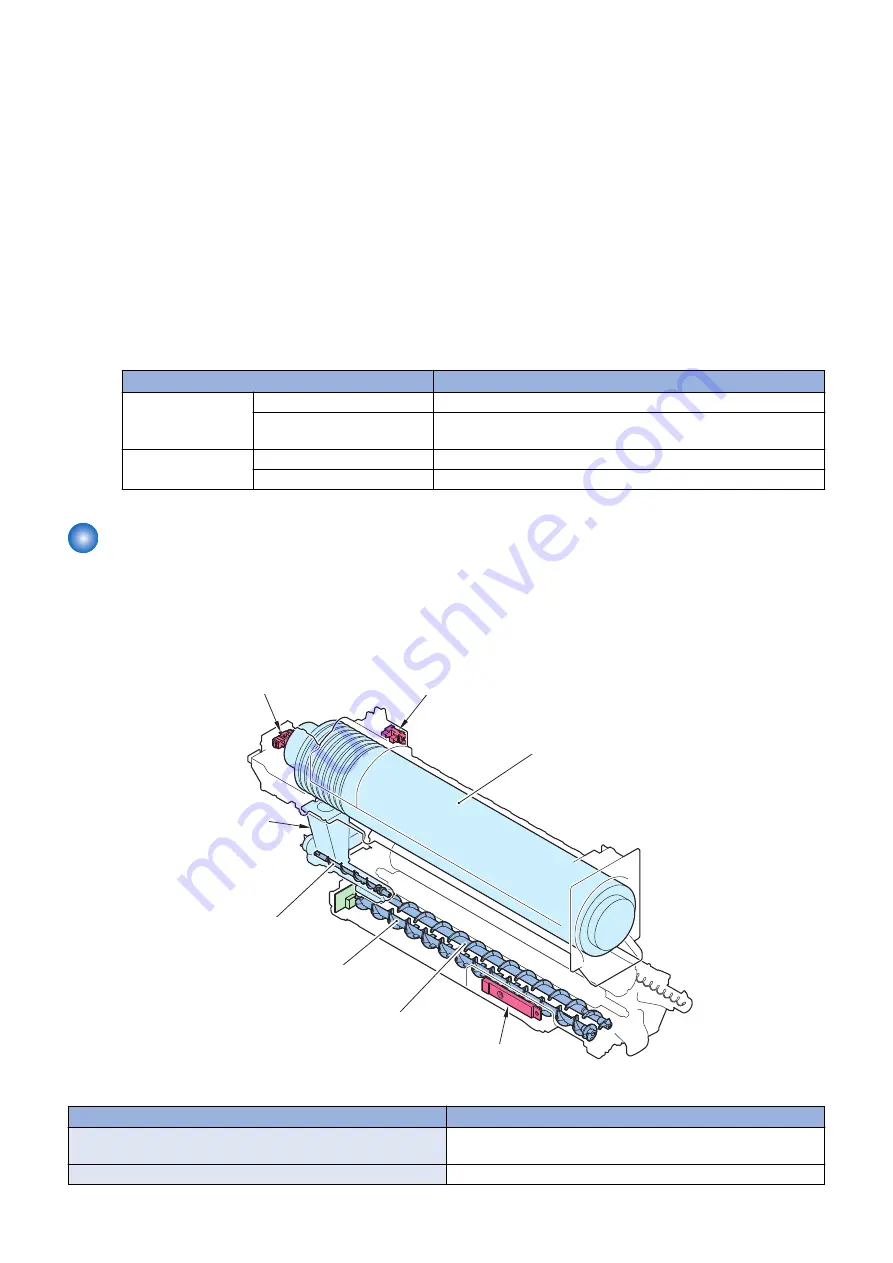
Toner Supply Assembly
■ Overview
Toner is supplied from the Toner Container to the Developing Assembly. The toner level in the Toner Container is detected at
the same time.
Hopper Unit
Bottle Rotation Sensor
(Y,M,C,Bk)
(PS6,7,8,9)
ATR Sensor
(Y,M,C,Bk)
(UN34,35,36,37)
Toner Container
Toner Feed Screw
Developer Feed Screw B
Developer Feed Screw A
Toner Log Connector
(Y,M,C,Bk)
(UN38,39,40,41)
Parts name
Role
Hopper Unit
Toner is supplied from the Toner Container to the Developing As-
sembly.
Toner Feed Screw
Toner is supplied from the Hopper Unit to the Developing Assembly.
2. Technology
67
Summary of Contents for imageRUNNER ADVANCE C255 Series
Page 1: ...Revision 2 0 imageRUNNER ADVANCE C355 C255 Series Service Manual ...
Page 17: ...Product Overview 1 Product Lineup 7 Option 8 Features 11 Specifications 14 Parts Name 18 ...
Page 127: ...Periodical Service 3 Periodically Replacement Parts 117 Consumable parts 118 ...
Page 154: ...4 Remove the Screws 5x 5 Remove the Rear Cover 1 4 Parts Replacement and Cleaning 143 ...
Page 257: ...1 Free the Harness 1 Harness Guide A 1x 1 A 4 Parts Replacement and Cleaning 246 ...
Page 376: ...Error Jam Alarm 7 Overview 366 EError Code 369 Jam Code 457 Alarm Code 464 ...
Page 469: ...Host Machine Cassette PS12 PS11 PS01 PS04 PS05 PS14 PS10 PS101 7 Error Jam Alarm 458 ...
Page 490: ...85 0005 For R D A Operation B Cause C Remedy 7 Error Jam Alarm 479 ...
Page 890: ...4 4x TP M3x6 5 3x 6 2x TP M3x6 7 8 9 Installation 879 ...
Page 891: ...9 1x 10 1x 11 2x 12 4x 13 9 Installation 880 ...
Page 903: ...17 9 Installation 892 ...
Page 914: ...5 6 2x Screw w washer M3x14 7 4x TP M3x6 9 Installation 903 ...
Page 923: ...3 2x 4 Short 1x 5 1x NOTE The removed screw will be used in step 7 6 1x 9 Installation 912 ...
Page 930: ...9 10 11 1x 12 13 9 Installation 919 ...
Page 931: ...14 2x 15 16 2x 17 6x 18 4x 9 Installation 920 ...
Page 932: ... Installing the NFC kit C1 1 1x 2 1x 3 TP M3x4 1x 9 Installation 921 ...