8
8
8-173
8-173
Service Mode > COPIER > ADJUST (Adjustment Mode) > CCD
Service Mode > COPIER > ADJUST (Adjustment Mode) > CCD
COPIER> ADJUST> CCD
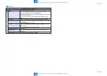
MTF2MCL
MTF VL in main scan way (color) [Back]
Lv.1 Details
If moire occurs in the image scanning during installation/scanner unit
replacement, increase the level one at a time.
Input the value on the service label during reader controller PCB
replacement/RAM clear.
Use case
• At the installation or replacement of scanner unit if moire occurs
on the read image.
• When the reader controller PCB is replaced or RAM is cleared.
Adj/set/operate method 1) Enter the setting value and press OK key.
2) Turn OFF/ON the main power switch.
Caution
Make sure to set CCD-CHG2 to “1” beforehand.
Display/adj/set range
0 to 4
0: correction ratio 100 %, 1: 95 %, 2: 90 %, 3: 85 %, 4: 80 %
Default value
0
Related service mode
COPIER> ADJUST> CCD> CCD-CHG2
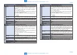
MTFSCL
MTF VL in sub scan way (color) [Front]
Lv.1 Details
If moire occurs in the image scanning during installation/scanner unit
replacement, increase the level one at a time.
Input the value on the service label during reader controller PCB
replacement/RAM clear.
Use case
• At the installation or replacement of scanner unit if moire occurs
on the read image.
• When the reader controller PCB is replaced or RAM is cleared.
Adj/set/operate method 1) Enter the setting value and press OK key.
2) Turn OFF/ON the main power switch.
Caution
Make sure to set CCD-CHNG to “1” beforehand.
Display/adj/set range
0 to 4
0: correction ratio 100 %, 1: 95 %, 2: 90 %, 3: 85 %, 4: 80 %
Default value
0
Related service mode
COPIER> ADJUST> CCD> CCD-CHNG
MTF2SCL
MTF VL in sub scan way (color) [back]
Lv.1 Details
If moire occurs in the image scanning during installation/scanner unit
replacement, increase the level one at a time.
Input the value on the service label during reader controller PCB
replacement/RAM clear.
Use case
• At the installation or replacement of scanner unit if moire occurs
on the read image.
• When the reader controller PCB is replaced or RAM is cleared.
Adj/set/operate method 1) Enter the setting value and press OK key.
2) Turn OFF/ON the main power switch.
Caution
Make sure to set CCD-CHG2 to “1” beforehand.
Display/adj/set range
0 to 4
0: correction ratio 100 %, 1: 95 %, 2: 90 %, 3: 85 %, 4: 80 %
Default value
0
Related service mode
COPIER> ADJUST> CCD> CCD-CHG2
COPIER> ADJUST> CCD
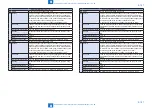
MTFMBW
MTF VL in main scan way (B&W) [Front]
Lv.1 Details
If moire occurs in the image scanning during installation/scanner unit
replacement, increase the level one at a time.
Input the value on the service label during reader controller PCB
replacement/RAM clear.
Use case
• At the installation or replacement of scanner unit if moire occurs
on the read image.
• When the reader controller PCB is replaced or RAM is cleared.
Adj/set/operate method 1) Enter the setting value and press OK key.
2) Turn OFF/ON the main power switch.
Caution
Make sure to set CCD-CHNG to “1” beforehand.
Display/adj/set range
0 to 4
0: correction ratio 100 %, 1: 95 %, 2: 90 %, 3: 85 %, 4: 80 %
Default value
0
Related service mode
COPIER> ADJUST> CCD> CCD-CHNG
MTF2MBW
MTF VL in main scan way (B&W) [Back]
Lv.1 Details
If moire occurs in the image scanning during installation/scanner unit
replacement, increase the level one at a time.
Input the value on the service label during reader controller PCB
replacement/RAM clear.
Use case
• At the installation or replacement of scanner unit if moire occurs
on the read image.
• When the reader controller PCB is replaced or RAM is cleared.
Adj/set/operate method 1) Enter the setting value and press OK key.
2) Turn OFF/ON the main power switch.
Caution
Make sure to set CCD-CHG2 to “1” beforehand.
Display/adj/set range
0 to 4
0: correction ratio 100 %, 1: 95 %, 2: 90 %, 3: 85 %, 4: 80 %
Default value
0
Related service mode
COPIER> ADJUST> CCD> CCD-CHG2
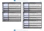
MTFSBW
MTF VL in sub scan way (B&W) [Front]
Lv.1 Details
If moire occurs in the image scanning during installation/scanner unit
replacement, increase the level one at a time.
Input the value on the service label during reader controller PCB
replacement/RAM clear.
Use case
• At the installation or replacement of scanner unit if moire occurs
on the read image.
• When the reader controller PCB is replaced or RAM is cleared.
Adj/set/operate method 1) Enter the setting value and press OK key.
2) Turn OFF/ON the main power switch.
Caution
Make sure to set CCD-CHNG to “1” beforehand.
Display/adj/set range
0 to 4
0: correction ratio 100 %, 1: 95 %, 2: 90 %, 3: 85 %, 4: 80 %
Default value
0
Related service mode
COPIER> ADJUST> CCD> CCD-CHNG
Summary of Contents for imagePRESS 1110
Page 242: ...3 3 Periodical Service Periodical Service Periodical service item ...
Page 655: ...5 5 Adjustment Adjustment Overview When replacing parts Major adjustment ...
Page 944: ...8 8 Service Mode Service Mode Overview COPIER FEEDER SORTER BOARD Situation Mode ...
Page 1555: ... Service Tools General Circuit Diagram General Timing Chart Operator Maintenance Appendix ...


