9
9
9-102
9-102
Installation > IPSec Board-B1/B2 > Installation Procedure
Installation > IPSec Board-B1/B2 > Installation Procedure
Installation Procedure
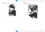
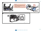
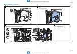
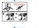
1) Remove the 3 screws from the controller cover.
x3
F-9-213
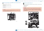
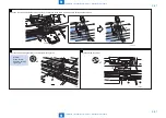
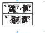
2) Remove the controller cover of the host machine in the direction of the arrow.
• 12 screws (loosen)
F-9-214
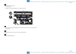
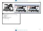
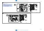
3) Install IPSec security PCB to PCI bus extension PCB.
• 2 screws
x2
F-9-215
4) Install the controller cover.
5) Insert the power plug into outlet.
6) Turn ON the main power switch.
Summary of Contents for imagePRESS 1110
Page 242: ...3 3 Periodical Service Periodical Service Periodical service item ...
Page 655: ...5 5 Adjustment Adjustment Overview When replacing parts Major adjustment ...
Page 944: ...8 8 Service Mode Service Mode Overview COPIER FEEDER SORTER BOARD Situation Mode ...
Page 1555: ... Service Tools General Circuit Diagram General Timing Chart Operator Maintenance Appendix ...

