9
9
9-118
9-118
Installation > Expansion Bus-F1/F2 > Installation Procedure
Installation > Expansion Bus-F1/F2 > Installation Procedure
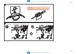
4) Install the PCI bus expansion PCB to the Riser support plate.
• 2 screws (TP; M3x6)
x2
F-9-247
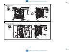
5) Install the PCI bus expansion PCB to the connector of main controller PCB 1.
• 3 screws (TP; M3x6)
x3
F-9-248
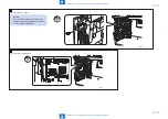
MEMO:
When installing the IP Sec security board,
install it before the step 6).
6) Install the controller cover.
7) Insert the power plug to the outlet.
8) Turn ON the main power switch.
Summary of Contents for imagePRESS 1110
Page 242: ...3 3 Periodical Service Periodical Service Periodical service item ...
Page 655: ...5 5 Adjustment Adjustment Overview When replacing parts Major adjustment ...
Page 944: ...8 8 Service Mode Service Mode Overview COPIER FEEDER SORTER BOARD Situation Mode ...
Page 1555: ... Service Tools General Circuit Diagram General Timing Chart Operator Maintenance Appendix ...


