


Chapter 7 Status and ZON
GS1920v2 Series User’s Guide
70
7.3 Zyxe l O ne Ne two rk (ZO N) Utility
ZON Utility is a program designed to help you deploy and manage a network more efficiently. It detects
devices automatically and allows you to do basic settings on devices in the network without having to
be near it.
The ZON Utility issues requests via Zyxel Discovery Protocol (ZDP) and in response to the query, the device
responds back with basic information including IP address, firmware version, location, system and model
name in the same broadcast domain. The information is then displayed in the ZON Utility screen and you
can perform tasks like basic configuration of the devices and batch firmware upgrade in it. You can
download the ZON Utility at www.zyxel.com and install it on a PC (Windows operating system).
7.3.1 Re q uire m e nts
Before installing the ZON Utility on your PC, please make sure it meets the requirements listed below.
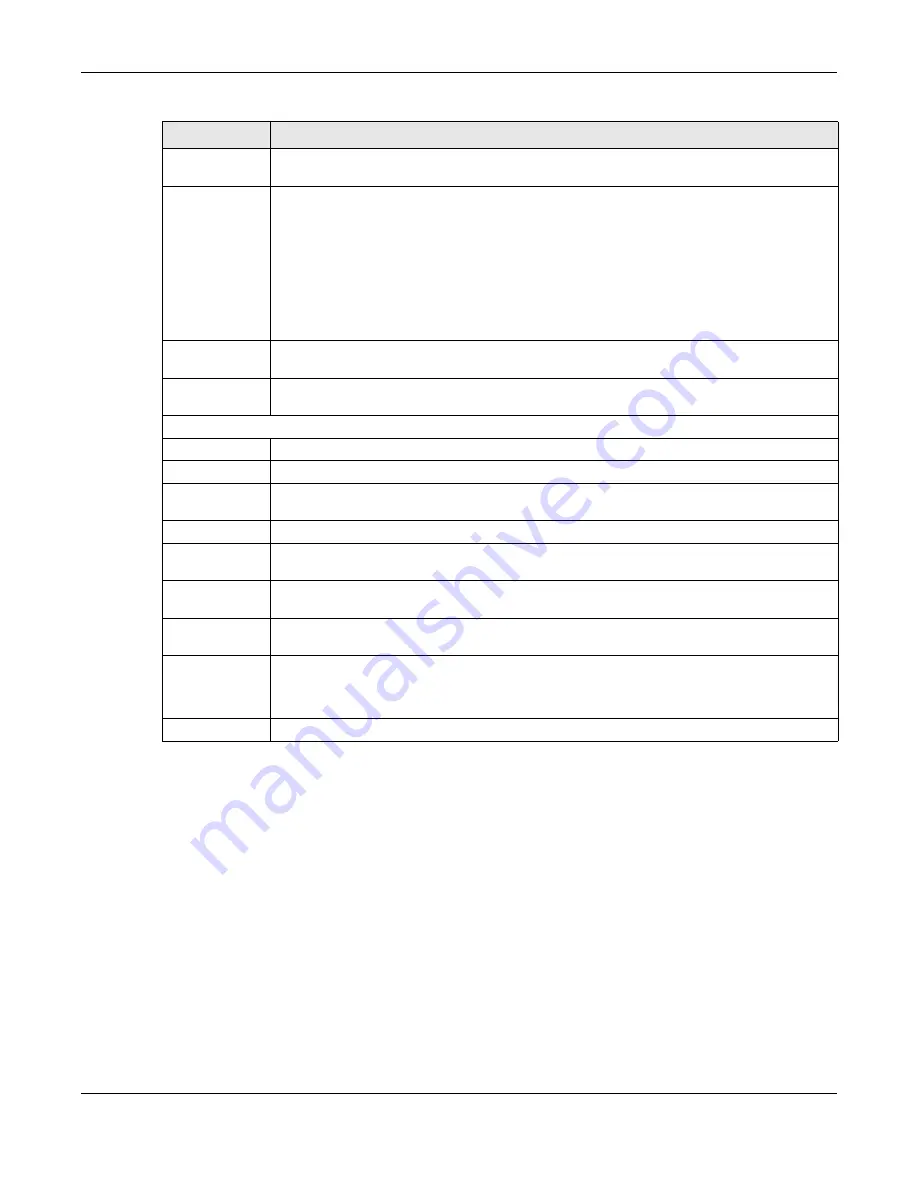
Hybrid Mode
This field displays whether the Switch is in
sta nda lo ne
mode or
c lo ud
mode. In
sta nda lo ne
mode
you can see a link to a QR code to register the Switch to use NCC (Nebula Control Center).
Cloud Control
Status
This field displays the registration and connection status between the Switch and the NCC
(Nebula Control Center). See
Section 3.3 on page 40
for more information on the Cloud LED.
In
sta nda lo ne
mode, the status will display
Disc o nne c te d
or
Unre g iste re d
. In
c lo ud
mode the
status will display
C o nne c te d
or
Disc o nne c te d
.
C o nne c te d
- The Switch is registered with and connected to the NCC.
Disc o nne c te d -
The Switch is not connected to the NCC.
Unre g iste re d
- The Switch is not registered with the NCC.
PoE Usage
This field displays the amount of power the Switch is currently supplying to the connected PoE-
enabled devices.
Detail
Click this link to go to the
Ba sic Se tting > Syste m Info
screen to check other detailed information,
such as system resource usage and the Switch temperature, fan speeds or voltage.
IP Address Information
IPv4 Address
This field displays the Switch’s current IPv4 address.
Subnet Mask
This field displays the Switch’s subnet mask.
Default
Gateway
This field displays the IP address of the Switch’s default gateway.
IP Setup
Click the link to go to the
Ba sic Se tting > IP Se tup
screen.
IPV6 Global
Unicast Address
This field displays the Switch’s IPv6 global unicast address
IPV6 Link-Local
Address
This field displays the Switch’s IPv6 link-local address.
IPv6
configuration
Click the link to go to the
Ba sic Se tting > IPv6
screen.
Device Status
and Quick
Configuration
This section shows whether a feature is enabled or not on the Switch. You can click a feature’s
Se tting
link to go to the configuration screen for the feature.
Hover your cursor over a red exclamation mark to display information about the feature.
Quick Links
This section provides the shortcut link to a specific configuration screen.
Table 9 Status (continued)
LABEL
DESC RIPTIO N
Содержание GS1920-48HPv2
Страница 19: ...19 PA RT I Use r s Guide...
Страница 43: ...43 PA RT II T e c hnic al Re fe re nc e...
Страница 124: ...Chapter 9 VLAN GS1920v2 Series User s Guide 124 Figure 97 Advanced Application VLAN Port Based VLAN Setup Port Isolation...
Страница 155: ...Chapter 13 Spanning Tree Protocol GS1920v2 Series User s Guide 155 Figure 118 MSTP and Legacy RSTP Network Example...
Страница 193: ...GS1920v2 Series User s Guide 193 Figure 140 Classifier Example...
Страница 224: ...Chapter 24 Multicast GS1920v2 Series User s Guide 224 Figure 162 MVR Group Configuration Example 2 EXAMPLE...
Страница 367: ...Chapter 40 Access Control GS1920v2 Series User s Guide 367 Figure 271 Example Lock Denoting a Secure Connection EXAMPLE...
Страница 388: ...Chapter 48 Configure Clone GS1920v2 Series User s Guide 388 Figure 284 Management Configure Clone...


