Chapter 5 Initial Setup Example
GS1920v2 Series User’s Guide
59
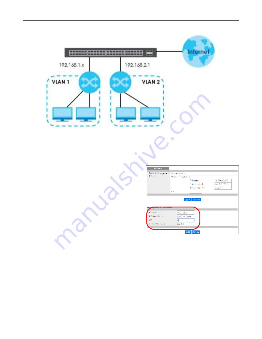
Fig ure 37
Initial Setup Example: Management IP Address
1
Connect your computer to any Ethernet port on the Switch. Make sure your computer is in the same
subnet as the Switch.
2
Open your web browser and enter 192.168.1.1 (the default IP address) in the address bar to access the
web configurator. See
Section 4.2 on page 44
for more information.
3
Click
Ba sic Se tting
>
IP Se tup
in the navigation
panel.
4
Configure the related fields in the
IP Se tup
screen.
5
For the
VLAN2
network, enter 192.168.2.1 as the IP
address and 255.255.255.0 as the subnet mask.
6
In the
VID
field, enter the ID of the VLAN group to
which you want this management IP address to
belong. This is the same as the VLAN ID you
configure in the
Sta tic VLAN
screen.
7
Click
Add
to save your changes back to the run-
time memory. Settings in the run-time memory are
lost when the Switch’s power is turned off.
Содержание GS1920-48HPv2
Страница 19: ...19 PA RT I Use r s Guide...
Страница 43: ...43 PA RT II T e c hnic al Re fe re nc e...
Страница 124: ...Chapter 9 VLAN GS1920v2 Series User s Guide 124 Figure 97 Advanced Application VLAN Port Based VLAN Setup Port Isolation...
Страница 155: ...Chapter 13 Spanning Tree Protocol GS1920v2 Series User s Guide 155 Figure 118 MSTP and Legacy RSTP Network Example...
Страница 193: ...GS1920v2 Series User s Guide 193 Figure 140 Classifier Example...
Страница 224: ...Chapter 24 Multicast GS1920v2 Series User s Guide 224 Figure 162 MVR Group Configuration Example 2 EXAMPLE...
Страница 367: ...Chapter 40 Access Control GS1920v2 Series User s Guide 367 Figure 271 Example Lock Denoting a Secure Connection EXAMPLE...
Страница 388: ...Chapter 48 Configure Clone GS1920v2 Series User s Guide 388 Figure 284 Management Configure Clone...


