Universal Slot PCB Wiring
Cable Lengths
Strata DK I&M 6/00
10-15
Universal Slot
PCB
Wi
ri
n
g
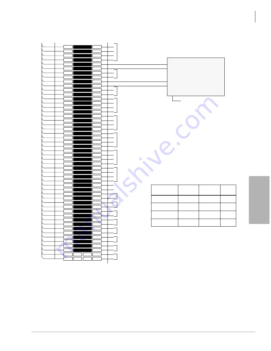
Figure 10-13 MDF Wiring/PEKU Amplified Two-CO Line Conference
1
2
3
4
5
6
7
8
9
10
11
12
13
14
15
16
17
18
19
20
21
22
23
24
25
26
27
28
29
30
31
32
33
34
35
36
37
38
39
40
41
42
43
44
45
46
47
48
49
50
1
2
3
4
5
6
7
8
9
10
11
12
13
14
15
16
17
18
19
20
21
22
23
24
25
26
27
28
29
30
31
32
33
34
35
36
37
38
39
40
41
42
43
44
45
46
47
48
49
50
W-BL
BL-W
W-O
O-W
W-GN
GN-W
W-BR
BR-W
W-S
S-W
R-BL
BL-R
R-O
O-R
R-GN
GN-R
R-BR
BR-R
R-S
S-R
BK-BL
BL-BK
BK-O
O-BK
BK-GN
GN-BK
BK-BR
BR-BK
BK-S
S-BK
Y-BL
BL-Y
Y-O
O-Y
Y-GN
GN-Y
Y-BR
BR-Y
Y-S
S-Y
V-BL
BL-V
V-O
O-V
V-GN
GN-V
V-BR
BR-V
V-S
S-V
26
1
27
2
28
3
29
4
30
5
31
6
32
7
33
8
34
9
35
10
36
11
37
12
38
13
39
14
40
15
41
16
42
17
43
18
44
19
45
20
46
21
47
22
48
23
49
24
50
25
Bridging
Clips
To PEKU W/Female
Connector
25-Pair Cable With Male Amp Connector
66M150 Split Block
Not Used
Not Used
Not USED
VT1
VR1
DT1
DR1
VT2
VR2
DT2
DR2
VT3
VR3
DT3
DR3
VT4
VR4
DT4
DR4
VT5
VR5
DT5
DR5
VT6
VR6
DT6
DR6
VT7
VR7
DT7
DR7
VT8
VR8
DT8
DR8
OT2
OR2
OT3
OR3
OT4
OR4
OT5
OR5
OT6
OR6
OT7
OR7
OT8
OR8
Circuit 8
Circuit 7
Circuit 6
Circuit 5
Circuit 4
Circuit 3
Circuit 2
OCA T1 (OT)
OCA R1 (OR)
Circuit 8 to EKT
or DSS
Circuit 7 to EKT
or DSS
Circuit 6 to EKT
Circuit 5 to EKT
or HDCB
Circuit 4 to EKT
Circuit 1 to EKT
PEKU, Circuit 2 Voice Pair
PEKU, Circuit 3 Voice Pair
Port A (CO Side)
Port B (Subscriber side)
(See Note 2)
Customer-supplied
Two-way amplifier
or
Line repeaters (see Note 1)
To 115 VAC ± 10 VAC
System Programs
• Program 10-3, circuit assignments:
Program 10-3
Button/LED
LED 01, ON
LED 02, ON
LED 03, ON
LED 04, ON
PEKU Slot
Position
2nd
3rd
4th
5th
PEKU Port
Number
A = 009
B = 010
PEKU
Circuit
A = 017
B = 018
A = 025
B = 026
A = 033
B = 034
CKT2
CKT3
CKT2
CKT3
CKT2
CKT3
CKT2
CKT3
1595
Notes
1.
Refer to Manufacturer’s installation
documentation for amplifier or line repeater
pin numbering.
2.
Connect to PEKU circuits only, do not connect
to PESU, PSTU, RSTU, RDSU or PDKU
circuits.
General Note
• Amplifier or repeater must have automatic gain
control and be registered FCC Part 68.
Program 10-1, button LED 19 and 20 ON.
Program 15-5, enable appropriate CO lines for
tandem connection.
Program 78-2, enable appropriate CO lines if
amplified DISA is required.
Program 10-2, key LED 18 and 19 ON.
Содержание Strata AirLink DK40i
Страница 22: ...Introduction Related Documents Media xx Strata DK I M 6 00 ...
Страница 48: ...DK14 Installation DK14 Wiring Diagrams 1 26 Strata DK I M 6 00 ...
Страница 220: ...DK424 Installation Remote Cabinet Installation Instructions 5 68 Strata DK I M 6 00 ...
Страница 262: ...DK424i Configuration Primary Reserve Power Cabinet Hardware 6 42 Strata DK I M 6 00 ...
Страница 450: ...Universal Slot PCB Wiring Option Interface PCB Wiring Diagrams 10 42 Strata DK I M 6 00 ...
Страница 592: ...Peripheral Installation Enhanced 911 Service E911 12 84 Strata DK I M 6 00 ...
Страница 616: ...ACD Installation Spectrum Electronic Wall Boards 13 24 Strata DK I M 6 00 ...
Страница 634: ...Fault Finding Fault Isolation Flowcharts 14 18 Strata DK I M 6 00 ...
Страница 704: ...ISDN Interfaces ISDN Disconnect Cause Code 16 54 Strata DK I M 6 00 ...


