ISDN Interfaces
RBSU/RBSS and TBSU Interface Units
16-26
Strata DK I&M 6/00
Most NT1 devices have TR option switches; if the NT1 does not have TRs, two 100-ohm TRs
must be wired into the NT1 modular jack - one 100-ohm resistor across each pair (Tx and Rx).
Refer to the NT1 manufacturers documentation for the maximum loop length between the NT1
and the network jack. The maximum loop length between the NT1 and the TBSU or RBSU circuit
is 1650 feet.
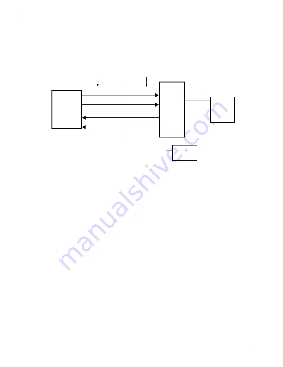
Figure 16-17 TBSU or RBSU to NT1 Point-to-point Connection
Connecting TBSU and RBSU/RBSS Station Devices (NT-Mode)
S-type TAs and TE-1s can be connected to the station side of TBSU, RBSU, and RBSS circuits.
TA and TE devices must be powered by local AC power using AC adapter supplied with the TA or
TE device. The TBSU and RBSU/RBSS circuits must be configured in the NT mode when
connected to TA and TE devices (refer to option switches in
and
and Program *60).
The TA enables you to connect non-ISDN voice and data devices to ISDN BRI circuits. The TA
matches the protocol of existing interfaces (R-reference point) to the ISDN S/T protocol (see
). TA devices include asynchronous circuit-switched adapters that convert
RS-232 async data (like data from a PC COM port) to B-channel 64 kbps sync.
TAs also enable you to connect standard telephones and non-ISDN fax machines to receive and
make calls over ISDN circuits. TEs include any user device (telephone, fax, PC video conference
board) that is designed to plug directly into the ISDN (S/T) interface without the use of a TA.
There are two types of ISDN TA and TE-1 devices: the U-type and the S/T type. Most
manufacturers of ISDN station devices make both types. In DK424 or DK424i R4.1 and DK40i,
the TBSU and RBSU/RBSS station side, BRI-NT circuits only function with S/T type TA and TE-
1 devices. You cannot connect U-type TE-1 or TA devices to the TBSU or RBSU/RBSS BRI-NT
circuits.
Also, connecting an NT1 to the TBSU or RBSU/RBSS BRI-NT circuit to convert from S/T to U
interface is not supported to enable the use of U-type TE-1 or TA device on the station side of the
TBSU or RBSU/RBSS. U-type TE-1 and TA device interface is provided in the DK by the TBUU
and RBUU/RBUS BRI circuit only. TBUU and RBUU/RBUS will be provided in the DK424 or
DK424i and DK40i Release 4.3.
TBSU or RBSU
TE-Circuit
Switch in
100-ohm TR
using RBSU
option switch.
RJ45 Pinout
(TBSU or RBSU - BRI jack)
3343
Network
BRI-line
RJ-11 Jack
NT-1
Switch
in 100-ohm
TR.
T and U are ISDN standard
reference points.
Note:
BRI
(four-wire)
T
BRI
(two-wire)
U
Demarcation Point
3
6
4
5
3
6
4
5
RX
RX
TX
RX
TX
TX
RX
TX
RX/TX
RX/TX
4
5
RJ45 Pinout
(NT1 - S/T jack)
Local AC
Power
Содержание Strata AirLink DK40i
Страница 22: ...Introduction Related Documents Media xx Strata DK I M 6 00 ...
Страница 48: ...DK14 Installation DK14 Wiring Diagrams 1 26 Strata DK I M 6 00 ...
Страница 220: ...DK424 Installation Remote Cabinet Installation Instructions 5 68 Strata DK I M 6 00 ...
Страница 262: ...DK424i Configuration Primary Reserve Power Cabinet Hardware 6 42 Strata DK I M 6 00 ...
Страница 450: ...Universal Slot PCB Wiring Option Interface PCB Wiring Diagrams 10 42 Strata DK I M 6 00 ...
Страница 592: ...Peripheral Installation Enhanced 911 Service E911 12 84 Strata DK I M 6 00 ...
Страница 616: ...ACD Installation Spectrum Electronic Wall Boards 13 24 Strata DK I M 6 00 ...
Страница 634: ...Fault Finding Fault Isolation Flowcharts 14 18 Strata DK I M 6 00 ...
Страница 704: ...ISDN Interfaces ISDN Disconnect Cause Code 16 54 Strata DK I M 6 00 ...


