DK14 Installation
Printed Circuit Board (PCB) Installation
Strata DK I&M 6/00
1-11
DK14 Installa
ti
on
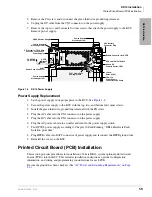
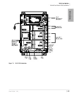
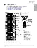
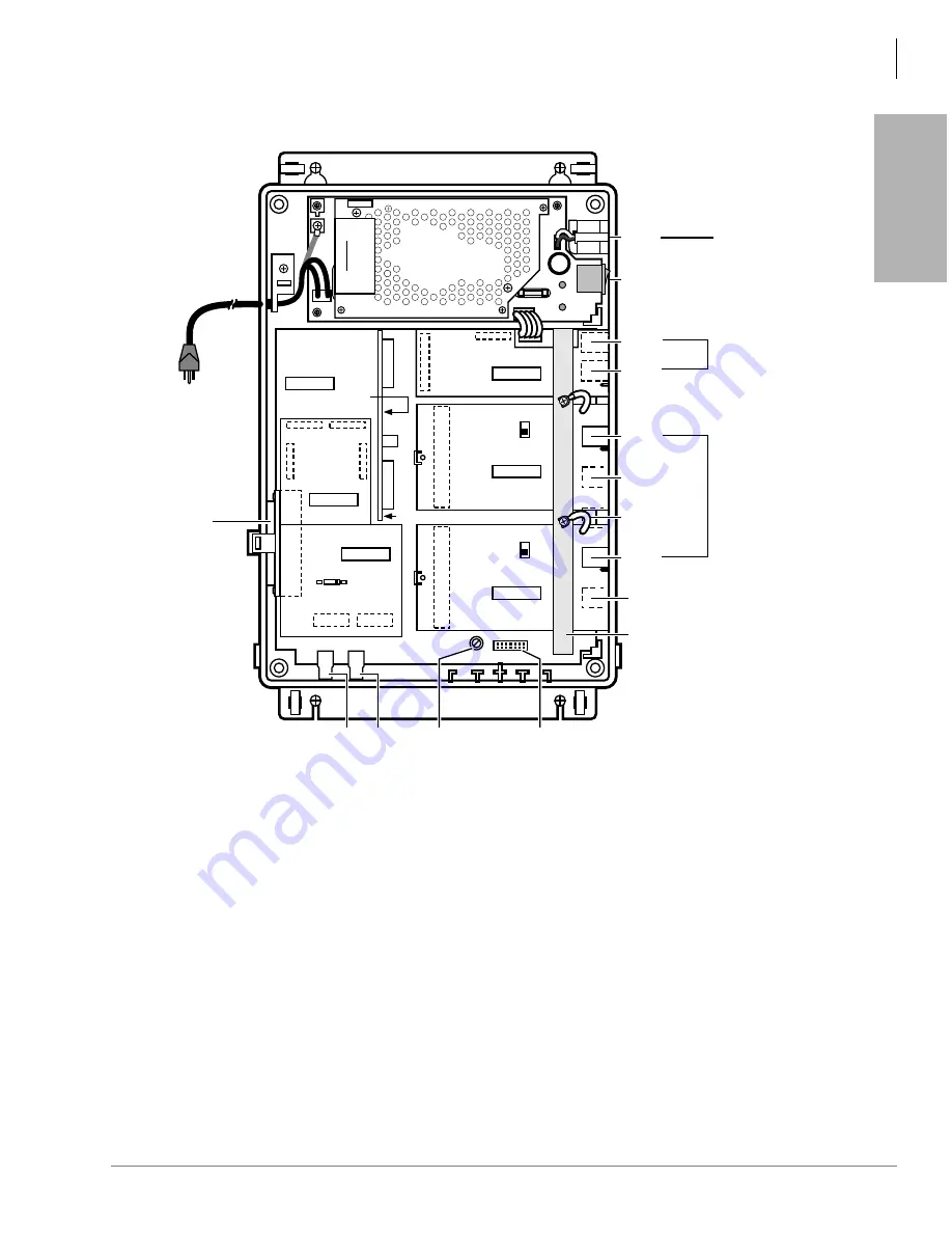
Figure 1-9
DK14 PCB Installation
J15
QSTS1A
J1
J11
J4
J14
J6
J8
J1
F.G.
STU
STU
J7
J5
WARNING
Hazardous voltage inside !
If servicing required,
remove A.C. cord.
HPFB6
QCDU2A
QKYS
J2
J10
J20
J3
J21
J4
J1
SW101
CO4
SIO 1
SIO 2
DC
BATT
QRCU3A
Component Side
CO2
J6-25 Pair
Amphenol Jack
(female) for
Telephone
Tip/Ring and
Relay Contact
CO3
CO1
PFT, RJ11
Modular
Jack
6-wire RJ11
Modular Jacks
6-wire RJ11
Modular Jack
1 or 2
HPFB reserve
power units
System
Frame
Ground
Bar
AC
DC
QCDU2A
MOH
Jack
MOH
Volume
Control
600
ohm
Page
Not
Used
F.G.
J9
J1
0 PAD 3
SW101
SW1
190 130
J2
STU
J12
J3
STU
J13
QSTU2A
QSTS2A
VR701
J22
2364
WSIU1A
0 PAD 3
Содержание Strata AirLink DK40i
Страница 22: ...Introduction Related Documents Media xx Strata DK I M 6 00 ...
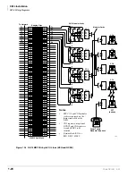
Страница 48: ...DK14 Installation DK14 Wiring Diagrams 1 26 Strata DK I M 6 00 ...
Страница 220: ...DK424 Installation Remote Cabinet Installation Instructions 5 68 Strata DK I M 6 00 ...
Страница 262: ...DK424i Configuration Primary Reserve Power Cabinet Hardware 6 42 Strata DK I M 6 00 ...
Страница 450: ...Universal Slot PCB Wiring Option Interface PCB Wiring Diagrams 10 42 Strata DK I M 6 00 ...
Страница 592: ...Peripheral Installation Enhanced 911 Service E911 12 84 Strata DK I M 6 00 ...
Страница 616: ...ACD Installation Spectrum Electronic Wall Boards 13 24 Strata DK I M 6 00 ...
Страница 634: ...Fault Finding Fault Isolation Flowcharts 14 18 Strata DK I M 6 00 ...
Страница 704: ...ISDN Interfaces ISDN Disconnect Cause Code 16 54 Strata DK I M 6 00 ...


