Universal Slot PCBs
RDTU – T1 Interface Unit
9-58
Strata DK I&M 6/00
External Options
W1 Ring Generator Switch Configuration (PSTU1 and PSTU2)
➤
On the PSTU1 or PSTU2, ensure the W1 switch is set to the “H” (190V P-P) position for
initial installation. The “L” (130V P-P) position is used if devices connected to the PSTU1 or
PSTU2 experience ring trip.
Standard Telephone Message Waiting Lamp Control
No steps required here.
RSTU2 Installation
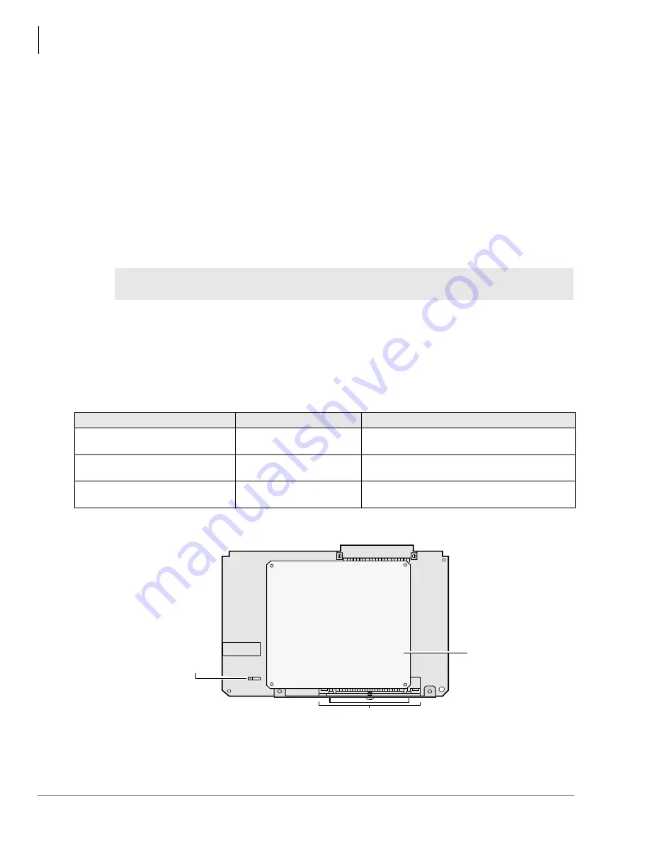
1. Make sure the factory-installed SSTS or SSTU subunit is securely attached to the RSTU2
(
).
2. Insert the RSTU2 (component side facing right) into the appropriate slot, and apply firm, even
pressure to ensure proper mating of connectors. RSTU2 must be installed per tables in
3. After installing the RSTU2, gently pull the RSTU2 outward. If the connectors are properly
mated, a light resistance is felt.
Figure 9-29 PSTU and Subunit (SSTU)
WARNING!
The shield on the back of the RSTU2 is designed to protect the installer from
potentially hazardous ring voltage. Do NOT remove this shield.
Table 9-19
RSTU2 Controls, Indicators, and Connectors
Control/Indicator/Connector
Type of Component
Description
Ring voltage W1 jumper (PSTU1
(V.4) and PSTU2 only)
3-terminal jumper
Sets ring generator voltage level for all circuits.
H=190V P-P, L=130V P-P.
R48S connector P6 (RSTU or
RSTU2 only)
9-pin connector
Interface connector to P6 of R48S.
R48S connector P7 (RSTU or
RSTU2 only)
6-pin connector
Interface connector to P7 of R48S.
SSTU
Subunit
W1
H
L
W1 Ring Voltage
H = 190V P-P
L = 130V P-P
(for PSTU (V.4)
and PSTU2 only)
Backplane Connector
50-Pin Amphenol Connector (Female)
1375
Содержание Strata AirLink DK40i
Страница 22: ...Introduction Related Documents Media xx Strata DK I M 6 00 ...
Страница 48: ...DK14 Installation DK14 Wiring Diagrams 1 26 Strata DK I M 6 00 ...
Страница 220: ...DK424 Installation Remote Cabinet Installation Instructions 5 68 Strata DK I M 6 00 ...
Страница 262: ...DK424i Configuration Primary Reserve Power Cabinet Hardware 6 42 Strata DK I M 6 00 ...
Страница 450: ...Universal Slot PCB Wiring Option Interface PCB Wiring Diagrams 10 42 Strata DK I M 6 00 ...
Страница 592: ...Peripheral Installation Enhanced 911 Service E911 12 84 Strata DK I M 6 00 ...
Страница 616: ...ACD Installation Spectrum Electronic Wall Boards 13 24 Strata DK I M 6 00 ...
Страница 634: ...Fault Finding Fault Isolation Flowcharts 14 18 Strata DK I M 6 00 ...
Страница 704: ...ISDN Interfaces ISDN Disconnect Cause Code 16 54 Strata DK I M 6 00 ...


