DK424 Configuration
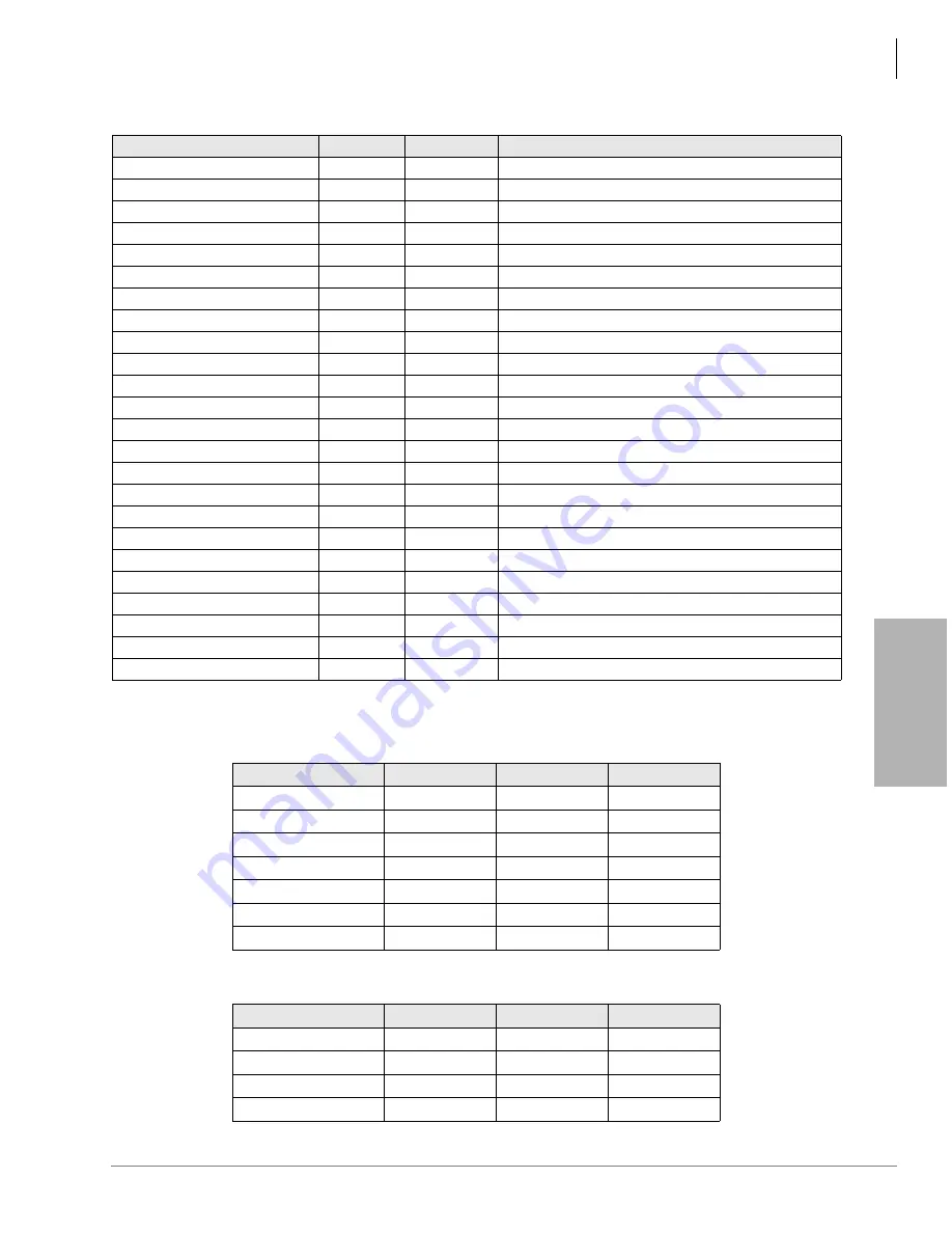
Worksheet 5 – System Power Factor Check
Strata DK I&M 6/00
4-35
DK424 Configur
at
ion
Note
Power factor calculation samples are shown in
.
Table 4-24
Strata DK424 Base Cabinet
Table 4-25
Strata DK424 Expansion Cabinet
RCTUB
4.0
1.0
RCTUBA/BB
4.0
1.9
RCTUC/D
4.5
1.9
RCTUE/F
10.0
1.9
RDDU
2.6
7.0
RDSU (-24VDC)
1.1
0.3
With 4 DKTs and 4 SLTs.
RDSU + R48S (-48VDC)
1.1
0.5
RDTU
1.8
1.0
REMU2/PEMU
1.0
7.5
RGLU1A/2A
2.1
2.5
RMCU1A
0.7
0.3
RMDS1A
0.35
0.16
2400 bps MODEM.
RPTU
2.6
1.0
RRCS-12
1.5
1.0
RRCS-4
0.4
0.3
RRCS-8
1.0
0.5
RRCU1A
4.5
0
RSIS1A
0.35
0.15
2400 bps.
RSIU1A
1.0
0.3
9600 bps.
RSSU
0.7
0.3
RSTU/RSTU2 (-24VDC)
1.4
0.5
With 8 SLTs.
RSTU1 + R48S (-48VDC)
1.4
1.0
With 8 SLTs.
RSTU2 + R48S (-48VDC)
4.0
2.3
With 8 MWs.
RWIU
9.2
0.0
With 8, 16, 24, or 32 handsets.
PCB
Quantity
+5VDC
-24VDC
PDKU2A
2
1.6
0.3
RBSS1A
1
3.2
0.3
RCOS1A
1
3.6
4.0 (8 COs)
RCTUA3A
1
2.0
1.0
RRCS1A-4
1
0.4
0.3
RWIU
1
9.0
0.0
Total
7
19.8
5.9
PCB
Quantity
+5VDC
-24VDC
RBSS1A
1
3.2
0.3
RSOU1A
1
3.6
4.0 (8 COs)
RWIU
2
18.0
0.0
Total
4
24.8
4.3
Table 4-23
PCB and Power Supply Power Factors
(continued)
PCB Type
+5VDC
-24VDC
Notes
Содержание Strata AirLink DK40i
Страница 22: ...Introduction Related Documents Media xx Strata DK I M 6 00 ...
Страница 48: ...DK14 Installation DK14 Wiring Diagrams 1 26 Strata DK I M 6 00 ...
Страница 220: ...DK424 Installation Remote Cabinet Installation Instructions 5 68 Strata DK I M 6 00 ...
Страница 262: ...DK424i Configuration Primary Reserve Power Cabinet Hardware 6 42 Strata DK I M 6 00 ...
Страница 450: ...Universal Slot PCB Wiring Option Interface PCB Wiring Diagrams 10 42 Strata DK I M 6 00 ...
Страница 592: ...Peripheral Installation Enhanced 911 Service E911 12 84 Strata DK I M 6 00 ...
Страница 616: ...ACD Installation Spectrum Electronic Wall Boards 13 24 Strata DK I M 6 00 ...
Страница 634: ...Fault Finding Fault Isolation Flowcharts 14 18 Strata DK I M 6 00 ...
Страница 704: ...ISDN Interfaces ISDN Disconnect Cause Code 16 54 Strata DK I M 6 00 ...

