T1
Applications
8-10
Strata DK I&M 6/00
Connecting the CSU to the Network Interface Unit (NIU) is specified by the CSU manufacturer—
see CSU installation documentation. Toshiba does not supply the cables and connectors required
to connect the CSU to the NIU (see
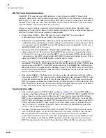
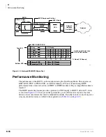
RDTU to PBX T1 (Separated More Than 655 ft.)
If the RDTU must interface to a customer’s premises T1 circuit (PBX, key/hybrid, or another DK)
to provide Tie line service, the RDTU must be connected to a CSU (with Toshiba NDTU cable) if
the other customer premise T1 equipment is more than 655 ft. from the RDTU. The T1 span on the
other end must also connect to a CSU.
Figure 8-4
RDTU Connection to Digital Network or OCC
The RDTU equalization switch (SW1) must be set for “SHORT” cable length because RDTU will
be connected to the CSU with the 30 ft. NDTU cable (see
Connecting CSU to CSU and CSU to the far-end PBX T1 is specified by the CSU manufacturer—
see the CSU installation documentation. Toshiba does not supply cables or connectors to connect
CSU to CSU (Cable A) or CSU to the far end PBX (Cable B).
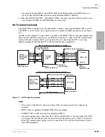
RDTU to PBX T1 (Separated Less Than 655 ft.)
If the RDTU is within 655 ft. of the far-end PBX T1 circuit, a CSU is not required. However,
connecting a RDTU T1 span to another PBX or Key/Hybrid T1, in a Tie line configuration at a
distance less than 655 ft. (without a CSU) will require a customer provided special cable. The
transmit and receive pair of this span cable must be separated by at least five cable pairs and the
wires must be 24 AWG, twisted pair, otherwise 22 AWG, ABAM type cable must be used. See
CSUs are not required if the RDTU is less than 655 ft. from the channel bank (see
Two CSUs (customer provided) are required if the RDTU is more than 655 ft. from the customer
premise channel bank (see
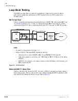
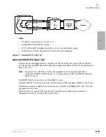
Strata DK
RDTU
CSU
DS-1
TOSHIBA
NDTU 30 ft Cable
Telco Digital Network or
Common Carrier
(AT&T, MCI, etc.)
Network
Interface
Unit
1665
Содержание Strata AirLink DK40i
Страница 22: ...Introduction Related Documents Media xx Strata DK I M 6 00 ...
Страница 48: ...DK14 Installation DK14 Wiring Diagrams 1 26 Strata DK I M 6 00 ...
Страница 220: ...DK424 Installation Remote Cabinet Installation Instructions 5 68 Strata DK I M 6 00 ...
Страница 262: ...DK424i Configuration Primary Reserve Power Cabinet Hardware 6 42 Strata DK I M 6 00 ...
Страница 450: ...Universal Slot PCB Wiring Option Interface PCB Wiring Diagrams 10 42 Strata DK I M 6 00 ...
Страница 592: ...Peripheral Installation Enhanced 911 Service E911 12 84 Strata DK I M 6 00 ...
Страница 616: ...ACD Installation Spectrum Electronic Wall Boards 13 24 Strata DK I M 6 00 ...
Страница 634: ...Fault Finding Fault Isolation Flowcharts 14 18 Strata DK I M 6 00 ...
Страница 704: ...ISDN Interfaces ISDN Disconnect Cause Code 16 54 Strata DK I M 6 00 ...


