T1
Slot Assignments
8-2
Strata DK I&M 6/00
RDTU - T1 Interface Unit
System:
DK424, DK424i
Circuits per PCB:
8, 16, or 24 channels
Interfaces with:
ground start CO lines
loop start CO lines
DID or Tie lines
Older Version(s):
none
RDTU is configured for Tie or DID lines and an RRCS must be installed for DTMF operation.
LEDs on the RDTU show a continuous status of RDTU operation.
Note
Each Tie or DID line decreases the system’s station port and CO line capacity by one.
♦
RCTUE/F and B5CAU/BU can support up to eight RDTU PCBs.
♦
RCTUC/D, B3CAU/BU and B2CAU/BU common control unit supports up to six RDTU
PCBs.
♦
RCTUB, RCTUBA/BB and B1CAU support up to two RDTU PCBs.
♦
RCTUA does not support the RDTU.
RDTU controls and interface connectors are shown in
The RDTU requires installation of a customer-provided Channel Service Unit (CSU). Refer to
for CSU installation.
Testing procedures (local loop back and remote loop back) are in
.
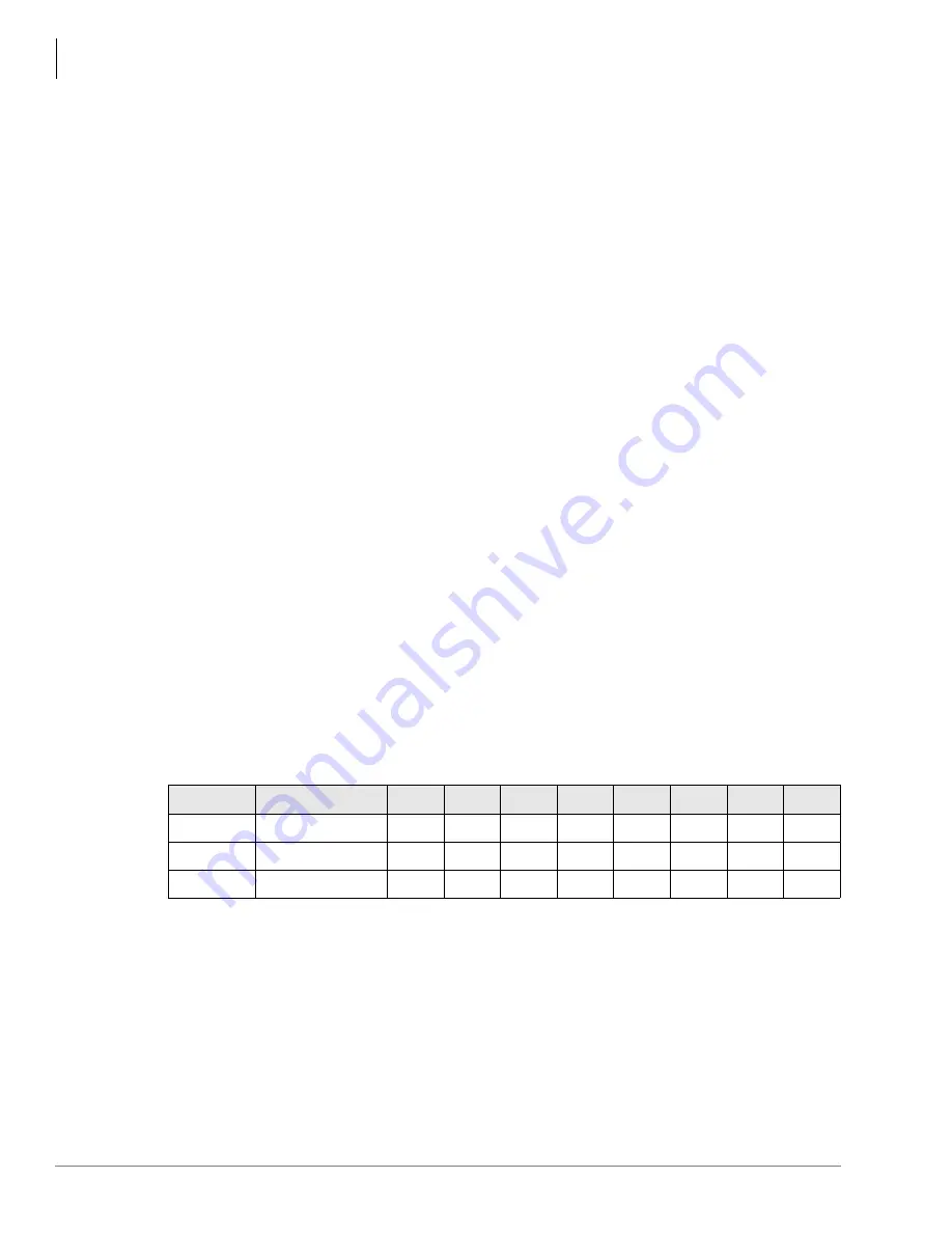
SW1 Equalizer Switch and Loop Back Jumpers (Internal Option)
The distance between the DK cabinets and the CSU (or other customer premise T1 circuit)
determines the setting of the SW1 Equalizer Switch. The SW1 switch consists of a bank of smaller
switches, S1~S7.
➤
Set the SW1 switch as follows:
Note
The maximum distance between the RDTU and the CSU or other T1 circuits can not be
more than 655 feet (see “RDTU to PBX T1 (Separated More Than 655 ft.)” on
RDTU Installation
Installing an RDTU (T1) into a Strata DK requires a number of system programs to be run.
Toshiba recommends running these programs in the order listed before actually installing the
RDTU into the system. This allows the RDTU to function immediately, including self-check loop
back testing and normal operation, when it is inserted into the system.
Mode
Feet from DK
S1
S2
S3
S4
S5
S6
S7
S8
Short
0~150
On
Off
Off
Off
Off
Off
Off
N/A
Medium
151~450
Off
On
Off
On
Off
On
Off
N/A
Long
450~655
Off
Off
On
Off
On
Off
On
N/A
Содержание Strata AirLink DK40i
Страница 22: ...Introduction Related Documents Media xx Strata DK I M 6 00 ...
Страница 48: ...DK14 Installation DK14 Wiring Diagrams 1 26 Strata DK I M 6 00 ...
Страница 220: ...DK424 Installation Remote Cabinet Installation Instructions 5 68 Strata DK I M 6 00 ...
Страница 262: ...DK424i Configuration Primary Reserve Power Cabinet Hardware 6 42 Strata DK I M 6 00 ...
Страница 450: ...Universal Slot PCB Wiring Option Interface PCB Wiring Diagrams 10 42 Strata DK I M 6 00 ...
Страница 592: ...Peripheral Installation Enhanced 911 Service E911 12 84 Strata DK I M 6 00 ...
Страница 616: ...ACD Installation Spectrum Electronic Wall Boards 13 24 Strata DK I M 6 00 ...
Страница 634: ...Fault Finding Fault Isolation Flowcharts 14 18 Strata DK I M 6 00 ...
Страница 704: ...ISDN Interfaces ISDN Disconnect Cause Code 16 54 Strata DK I M 6 00 ...


