Universal Slot PCBs
PCB Chapter Layout
Strata DK I&M 6/00
9-21
Universal Slot PCBs
PIOU2, PIOUS2 – Option Interface Units
System:
DK40i Expansion KSU, DK424, DK424i
Circuits per PCB:
(see interfaces)
Interfaces with:
night transfer/music hold control relay
door lock/external amplifier control relay
remote maintenance (IMDU)
TTY port–terminal, modem, SMDI, ACD/MIS (DK424 only)
SMDR output
alarm sensor
zone page interface–four zones (PIOU2 only)
built-in paging amplifier (PIOU2 only)
unamplified page output
Older Version(s):
none
The PIOU2 and PIOUS2 both provide a circuit interface with the system peripheral options. A
maximum of three PIOU2 or PIOUS2 PCBs can be installed in the system. (see
DK40i General Information:
On the DK40i, the Base KSU provides the 600 ohm page output;
the 600 ohm page output on the PIOU2, PIOUS2 is not used on the DK40i.
PIOU2 controls, indicators, and interface connectors are shown in
and described in
PIOUS2 information is provided in
IMDU Compatibility with PIOU and PIOUS
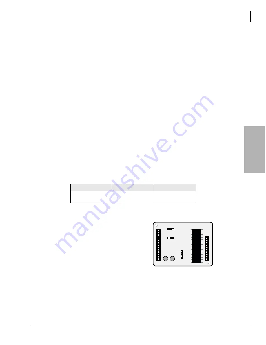
The compatibility of the IMDU1 and IMDU2A PCBs are shown in
IMDU2 Installation onto a PIOU2 or PIOUS2 (Internal Option)
1. Make sure IMDU2 P3 is set for PCM
Mu Law operation in the U.S and
Canada.
2. Make sure IMDU2 P1, modem transmit
gain is set on L in the U.S and Canada.
3. Make sure IMDU2 P2, modem receive
gain is set on L in the U.S and Canada.
4. On the PIOU2 or PIOUS2, set the SW3
switch to the “MODEM” position for
IMDU2 operation.
5. Set the P13 jumper plug on the PIOU2
or PIOUS2 to the “BELL.”
6. Mate IMDU2 connector J1 with PIOU2
or PIOUS2 connector P1 and IMDU2
J2 with P2 and P3 (see
Table 9-6
IMDU and PIOU/PIOUS Compatibility
PIOU/PIOUS
IMDU1
IMDU2A
PIOU1A/PIOUS1A
Available
Available
PIOU2A/PIOUS2A
N/A
Available
3651
J1
J2
P3
Mu A
P2
H
L
P1
HML
Figure 9-9
Remote Maintenance Modem
(IMDU2) Installation
Содержание Strata AirLink DK40i
Страница 22: ...Introduction Related Documents Media xx Strata DK I M 6 00 ...
Страница 48: ...DK14 Installation DK14 Wiring Diagrams 1 26 Strata DK I M 6 00 ...
Страница 220: ...DK424 Installation Remote Cabinet Installation Instructions 5 68 Strata DK I M 6 00 ...
Страница 262: ...DK424i Configuration Primary Reserve Power Cabinet Hardware 6 42 Strata DK I M 6 00 ...
Страница 450: ...Universal Slot PCB Wiring Option Interface PCB Wiring Diagrams 10 42 Strata DK I M 6 00 ...
Страница 592: ...Peripheral Installation Enhanced 911 Service E911 12 84 Strata DK I M 6 00 ...
Страница 616: ...ACD Installation Spectrum Electronic Wall Boards 13 24 Strata DK I M 6 00 ...
Страница 634: ...Fault Finding Fault Isolation Flowcharts 14 18 Strata DK I M 6 00 ...
Страница 704: ...ISDN Interfaces ISDN Disconnect Cause Code 16 54 Strata DK I M 6 00 ...


