T1
Hardware and Cabling
Strata DK I&M 6/00
8-13
T1
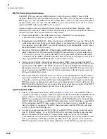
Secondary Reference RDTU, the PSYNC LED on the Primary Reference RDTU turns on
steady and the SSYNC LED on the Secondary Reference RDTU will flash.
♦
Run Free (PSYNC/SSYNC) – If the RDTU PCB is the clock provider to the Far-end T1 span
circuit both the PSYNC and SSYNC LEDs are always Off.
RDTU Cable Installation
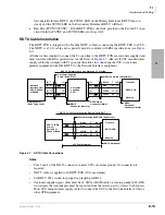
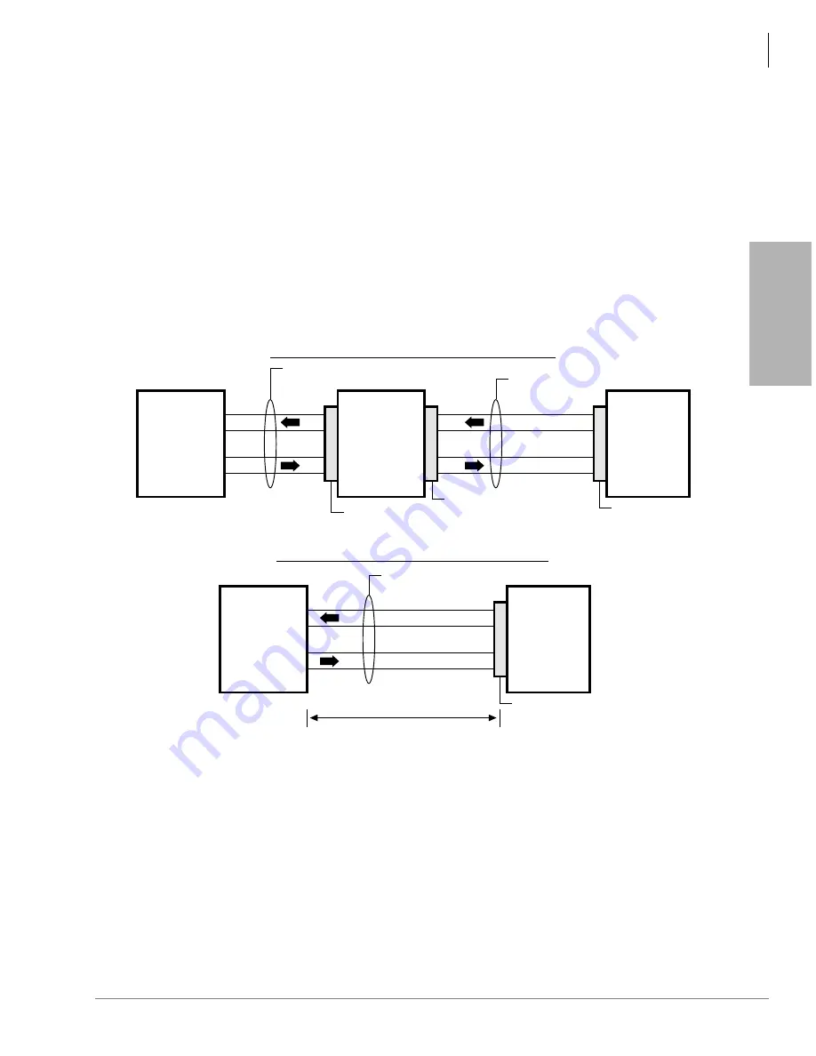
The RDTU PCB is shipped with a Toshiba NDTU cable for connecting the RDTU PCB to a CSU.
The NDTU is a 30 ft. cable and is specially made to conform with EIA specifications (see
All other cables required to connect the T1 span line to the RDTU PCB are customer-supplied and
must conform with EIA specification, see the Notes of
. Almost all CSU manufacturers
supply cables that comply with T1 span specifications for connecting the CSU to customer
premise equipment (like DK, RDTU) to the Network Interface equipment.
Figure 8-7
RDTU Cable Connections
Notes
●
Pins 2 and 4 of the DB-15 connector in most CSUs are frame ground. No connection is
required.
●
NDTU cable is supplied with RDTU PCB (30 ft. maximum).
●
Set RDTU SW1 switch for proper loop length per DK14.
●
Customer-supplied span cables must be 22 AWG, ABAM cable or, if using standard 24 AWG
twisted pair, the transmit pair must be separated from the receive pair by at least 5-cable pairs.
Most CSU manufacturers supply cables to connect the CSU to the Network Interface Unit or
other CPE equipment.
1670
RDTU PCB
(26)
(1)
(27)
(2)
T
R
T1
R1
Black
Red
White
Green
Customer-supplied Cable (See Notes)
RDTU To Customer Premise Equipment (CPE) T1
RDTU Amphenol
CPE T1 (PBX
or Key
System) or
Channel Bank
655 Feet Maximum
Transmit
Receive
(4) T
(5) R
(1) T1
(2) R1
Network
Interface Unit
USOC-RJ48C
or RJ48X
8-Pin Modular
(RJ45 Type Jack)
NDTU DB-15
Connector (Male)
DB-15
Connector (Female)
Customer Supplied
Cable (See Notes)
RDTU To Network or Long Distance T1 Provider
NDTU
Amphenol
Connector (Male)
(1)
(9)
(3)
(11)
Customer-
supplied
CSU
RDTU PCB
(26)
(1)
(27)
(2)
T
R
T1
R1
Black
Red
White
Green
(1)
(9)
(3)
(11)
NDTU Cable (30 ft. Maximum)
Transmit
Receive
Содержание Strata AirLink DK40i
Страница 22: ...Introduction Related Documents Media xx Strata DK I M 6 00 ...
Страница 48: ...DK14 Installation DK14 Wiring Diagrams 1 26 Strata DK I M 6 00 ...
Страница 220: ...DK424 Installation Remote Cabinet Installation Instructions 5 68 Strata DK I M 6 00 ...
Страница 262: ...DK424i Configuration Primary Reserve Power Cabinet Hardware 6 42 Strata DK I M 6 00 ...
Страница 450: ...Universal Slot PCB Wiring Option Interface PCB Wiring Diagrams 10 42 Strata DK I M 6 00 ...
Страница 592: ...Peripheral Installation Enhanced 911 Service E911 12 84 Strata DK I M 6 00 ...
Страница 616: ...ACD Installation Spectrum Electronic Wall Boards 13 24 Strata DK I M 6 00 ...
Страница 634: ...Fault Finding Fault Isolation Flowcharts 14 18 Strata DK I M 6 00 ...
Страница 704: ...ISDN Interfaces ISDN Disconnect Cause Code 16 54 Strata DK I M 6 00 ...


