DK424i Configuration
Architecture
6-2
Strata DK I&M 6/00
Architecture
The Base Cabinet and optional Expansion Cabinets are the building blocks of the system. Each
system has a Base Cabinet, and can have from one to four Expansion Cabinets. All lines, stations,
and options are tied together through the cabinets.
Processor PCBs
The system operates with one of four processors (B1CU, B2CAU/B2CBU, B3CAU/B3CBU, or
B5CAU/B5CBU). These processors can only be installed in dedicated slots in the Base Cabinet
(slots B101 and B102).
♦
B1CU – a single processor PCB that supports only the DK424i Base Cabinet with up to eight
universal slots.
♦
B2CAU/B2CBU – two PCBs that support up to two cabinets, with up to 14 universal slots.
Expansion Cabinet slots S207~S210 are
not
available with the B2CAU/B2CBU processors.
♦
B3CAU/B3CBU – two PCBs that support up to three cabinets, with up to 28 universal slots.
♦
B5CAU/B5CBU – two PCBs that supports up to five cabinets, with up to 48 universal slots.
Each processor provides a MOH/BGM source interface, and connectors to mount optional DTMF
receiver PCBs required for some CO line types and peripherals, as described below. Each
processor provides an interface for connecting an optional feature key (RKYS) as described below.
B3CAU/B3CBU and B5CAU/B5CBU require a remote maintenance PCB, usually installed in slot
S101; the remote maintenance PCB is optional for the B1CU and B2CAU/B2CBU.
lists the clock speed and available chips and memory for each processor.
Table 6-1
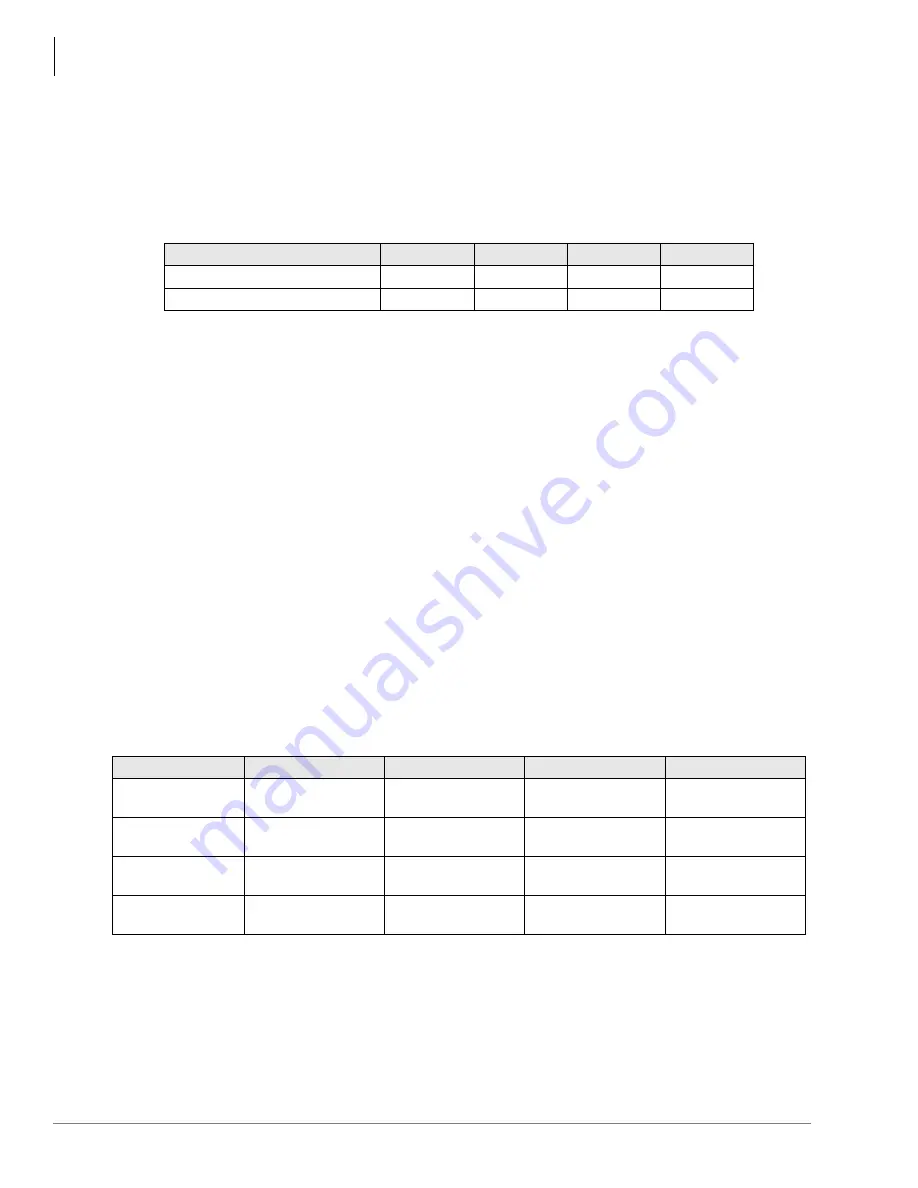
Cabinet Specifications
Cabinet
Weight
Height
Width
Depth
Base Cabinet (CHSUB672)
31 lbs.
11.65 in.
26.5 in.
10.6 in.
Expansion Cabinet (CHSUE672)
29 lbs.
10.0 in.
26.5 in.
10.6 in.
Table 6-2
Strata DK424i Processors and Memory
Cabinets
B1CU
B2CAU/B2CBU
B3CAU/B3CBU
B5CAU/B5CBU
Main CPU
68000
(8.192 MHz)
68000
(16.384 MHz)
68000
(16.384 MHz)
68EC020
(16.0 MHz)
Sub-CPU
TMP90C802-4011
x 1 (10MHz)
TMP90C802-4011
x 2 (10MHz)
TMP90C802-4011
x 3 (10MHz)
TMP90C802-4011
x 5 (10MHz)
Program Memory
2MB (4MB x 4)
EPROM
2MB (4MB x 4)
EPROM
2MB (4MB x 4)
EPROM
2 MB (4MB x 4)
Flash Memory
RAM
1MB (4MB x 2)
2MB (4MB x 4)
2MB (4Mb x 4)
2.5MB (4MB x
4 + 1MB x 4)
Содержание Strata AirLink DK40i
Страница 22: ...Introduction Related Documents Media xx Strata DK I M 6 00 ...
Страница 48: ...DK14 Installation DK14 Wiring Diagrams 1 26 Strata DK I M 6 00 ...
Страница 220: ...DK424 Installation Remote Cabinet Installation Instructions 5 68 Strata DK I M 6 00 ...
Страница 262: ...DK424i Configuration Primary Reserve Power Cabinet Hardware 6 42 Strata DK I M 6 00 ...
Страница 450: ...Universal Slot PCB Wiring Option Interface PCB Wiring Diagrams 10 42 Strata DK I M 6 00 ...
Страница 592: ...Peripheral Installation Enhanced 911 Service E911 12 84 Strata DK I M 6 00 ...
Страница 616: ...ACD Installation Spectrum Electronic Wall Boards 13 24 Strata DK I M 6 00 ...
Страница 634: ...Fault Finding Fault Isolation Flowcharts 14 18 Strata DK I M 6 00 ...
Страница 704: ...ISDN Interfaces ISDN Disconnect Cause Code 16 54 Strata DK I M 6 00 ...


