DK424i Configuration
Maximum Station/Line Capacities
6-4
Strata DK I&M 6/00
Expansion Cabinets
Expansion cabinets can be added to increase station and CO line capacity of systems that allow
multiple cabinets.
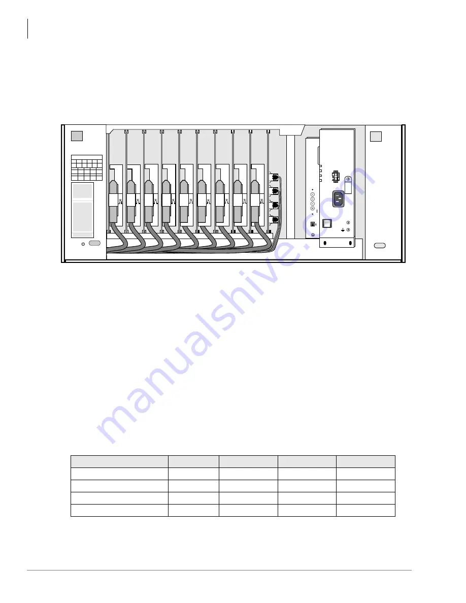
shows an example of the interior of an expansion cabinet.
Refer to the following section for station/line capacities.
shows the number of stations
and lines allowed when additional cabinets and PCBs are used.
Printed Circuit Boards (PCBs)
PCBs are installed in the cabinets to provide interface for stations, lines, and peripherals. Each
PCB measures 7.5 x 5.5 inches (190 x 140 mm) and mounts in the slot with a 44-pin backplane
connector. PCB external connections to station equipment are made to the Main Distribution
Frame (MDF) using industry-standard connectors.
Maximum Station/Line Capacities
Attaining maximum system capacities depends on power consumption of a particular
configuration. Configurations for a fully expanded system can range from 200 lines or 336
stations. One universal slot is required for Remote Maintenance PCB with B3CAU/B3CBU and
B5CAU/B5CBU, but is optional for B1CU and B2CAU/B2CBU.
A summary of the maximum number of lines and stations by processor is shown in
.
Table 6-4
Strata DK424i Maximum Capacities
Cabinets
B1CU
B2CAU/B2CBU
B3CAU/B3CBU
B5CAU/B5CBU
Maximum CO Lines
32
104
120
200
Maximum Stations
56
112
192
336
St Analog Lines
56 or 64*
104 or 112*
216
376
St T1 &/or PRI Lines
64
128
248
432
* Configuration numbers marked with a * do not include a slot for the Remote Maintnenace PCB. All other
configurations (without an *) assume that a slot is provided for the Remote Maintenance PCB.
S_01
S_02
S_03
S_04
S_05
S_06
S_07
S_08
S_09
S_10
5003
CABINET NO.
2
S_01
S_02
S_03
S_04
S_05
S_06
S_07
S_08
S_09
S_10
3
4
5
6
7
POW
+5V
-5V
P.F.
RESET
EXP
BASE
AC IN
AC IN
DC OUT
-27V1
-27V2
-27V3
-27V4
+
-
POWER
ON
OFF
FG
5002
POW
+5V
-5V
P.F.
RESET
EXP
BASE
AC IN
BATT
DC OUT
-27V1
-27V2
-27V3
-27V4
+
-
POWER
ON
OFF
FG
5002
Figure 6-3
DK424i Expansion Cabinet Interior
Содержание Strata AirLink DK40i
Страница 22: ...Introduction Related Documents Media xx Strata DK I M 6 00 ...
Страница 48: ...DK14 Installation DK14 Wiring Diagrams 1 26 Strata DK I M 6 00 ...
Страница 220: ...DK424 Installation Remote Cabinet Installation Instructions 5 68 Strata DK I M 6 00 ...
Страница 262: ...DK424i Configuration Primary Reserve Power Cabinet Hardware 6 42 Strata DK I M 6 00 ...
Страница 450: ...Universal Slot PCB Wiring Option Interface PCB Wiring Diagrams 10 42 Strata DK I M 6 00 ...
Страница 592: ...Peripheral Installation Enhanced 911 Service E911 12 84 Strata DK I M 6 00 ...
Страница 616: ...ACD Installation Spectrum Electronic Wall Boards 13 24 Strata DK I M 6 00 ...
Страница 634: ...Fault Finding Fault Isolation Flowcharts 14 18 Strata DK I M 6 00 ...
Страница 704: ...ISDN Interfaces ISDN Disconnect Cause Code 16 54 Strata DK I M 6 00 ...


