C
L E A R
P
A T H
M C / S D
U
S E R
M
A N U A L
R
E V
.
3 . 0 9
9 9
T
EKNIC
,
I
NC
. T
EL
.
(585)
784-7454
R
AMP
U
P
/D
OWN
T
O
S
ELECTED
V
ELOCITY
M
ODE
D
ESCRIPTION
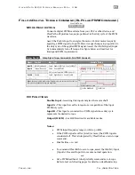
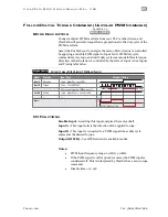
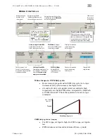
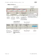
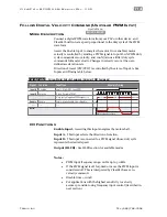
Changing the digital inputs on ClearPath (using your PLC, switches, etc.)
causes ClearPath to smoothly ramp between any of four user defined
velocities.
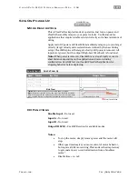
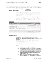
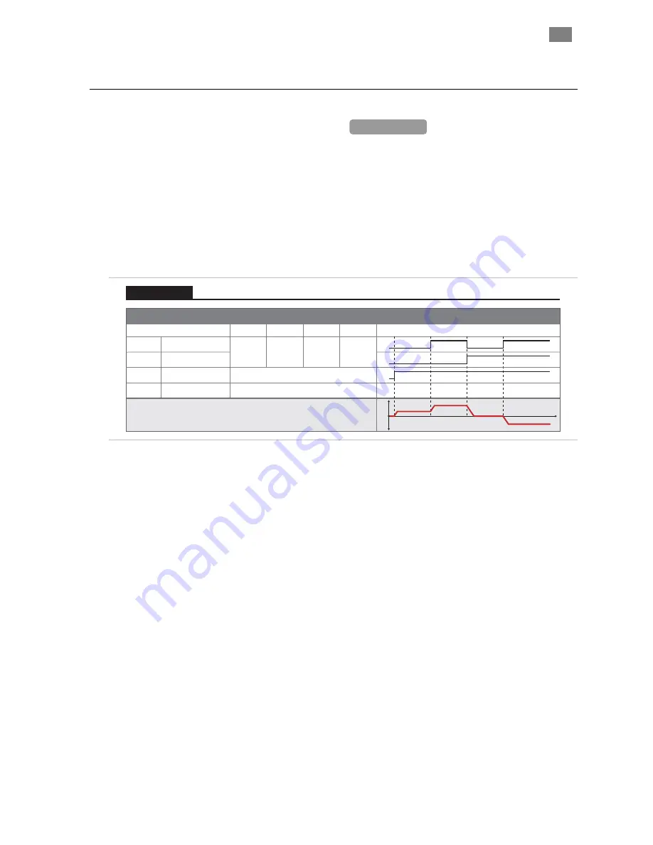
Assert the Enable Input to get started. Once enabled, ClearPath reads the
state of Inputs A and B and immediately accelerates to the target velocity
indicated. For example, if
Input A is high
and
Input B is low
ClearPath will ramp to “Velocity 2”. Change to a different velocity by
changing Inputs A and B
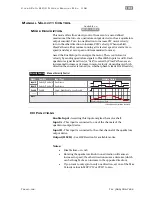
Signal
Function
Velocity Settings (logic levels)
Example Timing
Input A
Motor velocity vs. time
Input B
Enable
Velocity Select A
Velocity Select B
Enable
NA
NA
Trigger
Logic: High=Enable Low=Disable
0
1
0
1
0
1
0
1
t
v
0
Velocity 1 Velocity 2 Velocity 3 Velocity 4
LOW
LOW
HIGH
LOW
LOW
HIGH
HIGH
HIGH
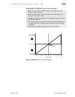
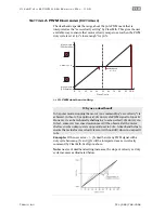
Tip:
Setting one of the programmable velocities to zero (Velocity 3 in the example
at right) provides a convenient way to stop the motor via the ClearPath inputs.
Velocity 1
Velocity 2
Velocity 3
Velocity 4
Ramp Up/Down to Selected Velocity (4 Velocity Programmable)
Velocity Control
Ramp Up/Down to Selected Velocity Mode: Inputs and Timing Diagram
I/O
F
UNCTIONS
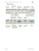
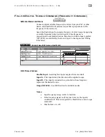
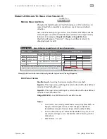
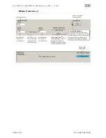
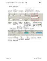
Enable Input -
Asserting this input energizes the motor shaft.
Input A -
This input, along with Input B, selects which of the four defined
velocities ClearPath will run at.
Input B -
This input, along with Input A, selects which of the four defined
velocities ClearPath will run at.
Output (HLFB) -
See HLFB section for available modes.
Notes:
•
As soon as a new velocity command is received by ClearPath—as
happens when Inputs A and/or B are changed—ClearPath
immediately ramps to the new target velocity without delay.
•
For a convenient way to command ClearPath to stop, set one of
the velocity settings to zero. We did this with “Velocity 3” in the
table above.
•
Disable time = 10 mS
MCVC + MCPV
Available on

