C
L E A R
P
A T H
M C / S D
U
S E R
M
A N U A L
R
E V
.
3 . 0 9
1 3 8
T
EKNIC
,
I
NC
. T
EL
.
(585)
784-7454
P
ULSE
B
URST
P
OSITIONING
M
ODE
D
ESCRIPTION
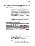
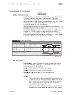
ClearPath will move a distance proportional to the number of pulses sent
to Input B. This mode offers much of the flexibility of a “step-and-
direction” system, without the need for an expensive indexer to create
smooth move trajectories (that function is handled by ClearPath’s internal
trajectory generator). This mode is limited to two speeds and one
acceleration/deceleration rate set by the user.
Note:
A fairly simple PLC counter or a software loop can be used to
generate pulses for use with this mode.
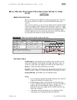
Assert the Enable Input to energize the motor. (Note: ClearPath can be
configured to perform a homing routine upon enable.) To execute
positioning moves, send a high speed stream of pulses to Input B, where
each pulse represents an incremental unit of distance. Total move distance
is determined by the number of pulses sent to Input B.
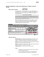
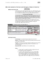
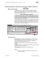
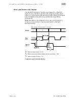
Signal
Function
Input Type
Input A
Motor velocity vs. time
Input B
Enable
Direction Select
Pulse Input
Enable
Speed Select
Pulse low to select alternate speed
Trigger
Logic: High=CW Low=CCW
Pulse: High-Speed Pulse Burst
Logic: High=Enable Low=Disable
0
1
0
1
t
v
Example Timing
Notes:
ClearPath requires a
minimum pulse width =
1uS
. Pulses less than < 1uS
will be filtered out as noise by ClearPath.
0
1
Trigger pulse
cc_mcsd
Pulse Burst Positioning
Pulse Positioning
alternate speed
I/O
F
UNCTIONS
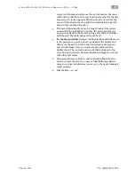
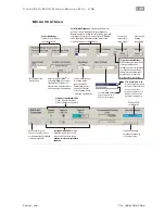
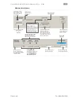
Enable Input -
Asserting this input energizes the motor shaft. A short
pulse (user-definable) on this input tells ClearPath to use the alternate
speed limit setting for the next move.
Input A -
This input selects the direction of rotation.
Input B -
This input is connected to the pulse source.
Output (HLFB) -
See HLFB section for available modes.
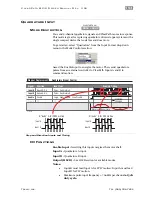
Notes:
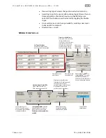
•
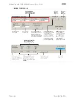
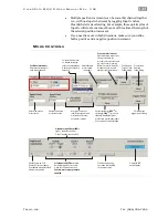
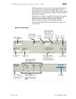
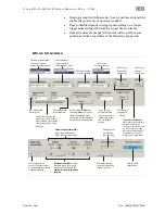
The frequency of the pulse train applied to Input B must always
be higher than the specified speed limit(s). This ensures that the
motor's pulse buffer is never empty. See the “Burst Frequency
Spec” (circled in red on the figure below) for the range of
allowable pulse input frequencies.
•
Sending pulses at a fixed frequency is OK; in fact, this is one of
the reasons why this mode was developed. Just send a burst of
MCPV
Available on

