C
L E A R
P
A T H
M C / S D
U
S E R
M
A N U A L
R
E V
.
3 . 0 9
1 5 0
T
EKNIC
,
I
NC
. T
EL
.
(585)
784-7454
O
PERATIONAL
M
ODES
:
SDSK
AND
SDHP
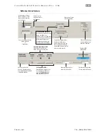
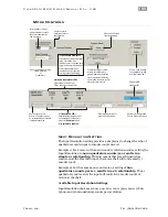
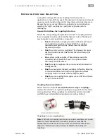
The ClearPath SD (Step & Direction) family was designed to replace
stepper motor and drive systems with a single, cost-effective unit.
Note: ClearPath SDSK and SDHP models accept
quadrature AB
signal
sources as well as
step & direction
signals.
S
TEP
&
D
IRECTION
M
ODE
D
ESCRIPTION
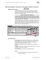
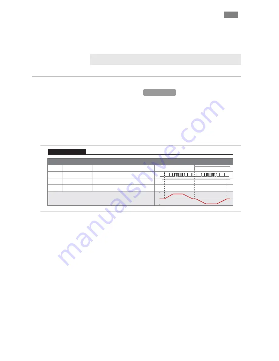
Enable your ClearPath and send industry standard step & direction
signals to Inputs A and B, and ClearPath faithfully follows them. Use the
included RAS (Regressive Auto Spline) feature to reduce vibration and
noise. This mode is great for replacing stepper motor and drive systems
with a single, compact device that costs less and does more.
ClearPath SD models require step and direction signals generated from an
external device such as an indexer, microcontroller, or similar.
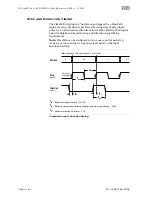
Signal
Function
Input Type
Input A
Motor velocity vs. time
Input B
Enable
Direction
Step
Enable
NA
NA
Trigger
Logic: High=CW Low=CCW
Pulse: Digital Step Input
Logic: High=Enable Low=Disable
0
1
0
1
t
v
Example Timing
Notes:
ClearPath requires a
minimum pulse width =
1uS
. Pulses less than < 1uS
will be filtered out as noise by ClearPath.
0
1
0
1
Step and Direction Input Control
Stepper Replacement
all_cpm
Step and Direction Inputs and Timing
I/O
F
UNCTIONS
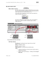
Enable Input -
Asserting this input energizes the motor shaft.
Input A -
Direction input.
Input B -
Step input.
Output (HLFB) -
See HLFB section for available modes.
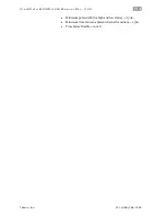
Notes:
•
Minimum pulse width (for high and low states) = 715 nS.
•
Maximum pulse input frequency = 700kHz
at 50% duty
cycle.
•
Motion occurs on the rising edge of each step input pulse.
•
Time before Disable = 10 mS.
SDSK + SDHP
Available on

