C
L E A R
P
A T H
M C / S D
U
S E R
M
A N U A L
R
E V
.
3 . 0 9
4 4
T
EKNIC
,
I
NC
. T
EL
.
(585)
784-7454
C
LEAR
P
ATH
I
NPUTS
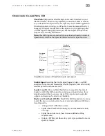
The three inputs, designated
Enable
,
Input A
, and
Input B
, are designed
for use with 5-24VDC logic levels and pulses from a wide variety of signal
sources and devices including PLCs, microcontrollers, and even
mechanical switches, with no external resistors required.
Enable-
4
8
Input A+
Input A-
3
7
Input B+
Input B-
2
6
Current
Limiter
Current
Limiter
Current
Limiter
5-24
VDC
5-24
VDC
5-24
VDC
ClearPath Internal
External Circuit
+
+
+
ClearPath Inputs shown with simple switches
I
NPUT
C
URRENT
D
RAW
The table and graph below illustrate the maximum current draw by the
ClearPath input circuits for the range of acceptable input voltages.
Voltage at
ClearPath Input
Minimum Input
Current Required
5 VDC
8 mA
12 VDC
9 mA
24 VDC
12 mA
Min. Input Current (mA)
5
9 12 16
24
Input Voltage (VDC)
12
10
11
9
8
20
Maximum input current draw at given input voltages

