C
L E A R
P
A T H
M C / S D
U
S E R
M
A N U A L
R
E V
.
3 . 0 9
1 0 3
T
EKNIC
,
I
NC
. T
EL
.
(585)
784-7454
M
ANUAL
V
ELOCITY
C
ONTROL
M
ODE
D
ESCRIPTION
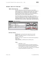
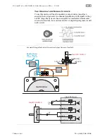
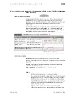
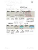
This mode offers fine velocity control from zero to a user-defined
maximum at the turn of a quadrature output device (such as a quadrature
output encoder). Turn in one direction to increase CW motor velocity;
turn in the other direction to increase CCW velocity. When enabled,
ClearPath can either resume running at its last set speed
or
start at zero
speed (and stay at zero speed until commanded to move).
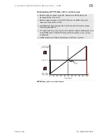
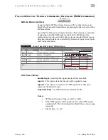
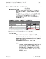
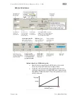
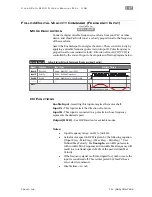
Assert the Enable Input to energize the motor. Then, control motor
velocity by sending quadrature signals to ClearPath Inputs A and B. Each
quadrature signal transition (or “tick”) received by ClearPath causes an
incremental increase or decrease in motor velocity, depending on which
direction the encoder is turned (i.e. whether phase A leads B or B leads A).
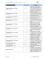
Signal
Function
Input Type
Input A
Motor velocity vs. time
Input B
Enable
Velocity Control A
Velocity Control B
Enable
NA
NA
Trigger
Quadrature
Quadrature
Logic: High=Enable Low=Disable
0
1
0
1
0
1
t
v
Example Timing
Notes:
Manual Velocity Control
Velocity Control
Knob/encoder rotation reversed
I/O
F
UNCTIONS
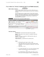
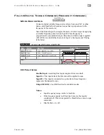
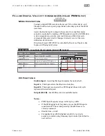
Enable Input -
Asserting this input energizes the motor shaft.
Input A -
This input is connected to one of the channels of the
quadrature output device.
Input B -
This input is connected to the other channel of the quadrature
output device.
Output (HLFB) -
See HLFB section for available modes.
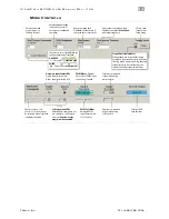
Notes:
•
Disable time = 10 mS
•
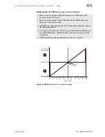
Rotating the quadrature knob in one direction will cause an
increase in speed; the other direction causes a decrease (which
can be thought of as an increase in the opposite direction).
•
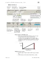
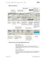
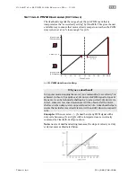
If you want to only spin in only one direction, set one of the Max
Velocity values in MSP (CW or CCW) to zero.
MCVC + MCPV
Available on


