C
L E A R
P
A T H
M C / S D
U
S E R
M
A N U A L
R
E V
.
3 . 0 9
1 4 6
T
EKNIC
,
I
NC
. T
EL
.
(585)
784-7454
F
OLLOW
D
IGITAL
P
OSITION
C
OMMAND
:
U
NIPOLAR
PWM
C
OMMAND
M
ODE
D
ESCRIPTION
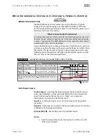
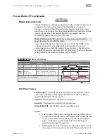
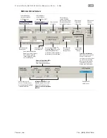
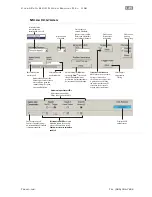
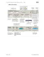
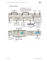
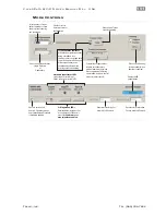
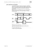
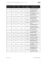
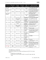
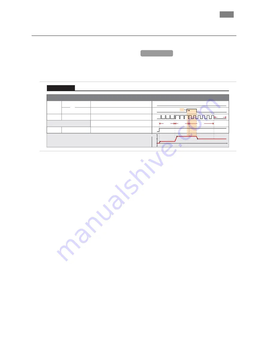
ClearPath will servo to a position between two user-defined limits
proportional to the PWM duty cycle of the signal on input B.
Signal
Function
Input Type
Input A
Motor position (as % of total span) vs. time
Enable
Home Sensor
Command Lock
Enable
Logic: High=In Sensor Low=Not in Sens.
Logic: High=Lock ON Low=Lock OFF
Logic: High=Enable Low=Disable
0
1
0
1
t
Example Timing
Notes:
Home sensor not used in this example. See Homing section for details.
0
1
0
1
Duty cycle of applied PWM signal (%)
80%
50%
20%
OFF
or
0%
100%
50%
80%
20%
Cmd. Lock = ON
Input B
Position
Pulse: Variable PWM
0
1
Follow Digital Position: Unipolar PWM Command
Position Control
I/O
F
UNCTIONS
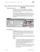
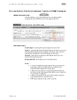
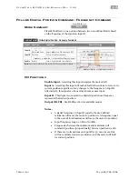
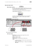
Enable Input -
Asserting this input energizes the motor shaft.
Input A -
Asserting this input will make ClearPath continue to servo to its
current position regardless of any changes to the duty cycle on Input B.
Alternatively, this signal can be used as a home sensor input.
Input B -
This input is connected to a PWM signal whose duty cycle
represents the desired position.
Output (HLFB) -
See HLFB section for available modes.
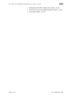
Notes:
•
A loss of modulation (meaning Input B has no transitions for
more than 50 ms) is considered an error condition, and
ClearPath will maintain its current position.
•
A duty cycle of nearly 0% or 100% (with a state transition at
least every 50 ms) will command ClearPath to move to position
0 or position 1, respectively.
•
A duty cycle between 0% and 100% will command a position
proportionally between position 0 and 1.
•
PWM input frequency range: 20 Hz to 30 kHz.
MCPV
Available on


