C
L E A R
P
A T H
M C / S D
U
S E R
M
A N U A L
R
E V
.
3 . 0 9
4 7
T
EKNIC
,
I
NC
. T
EL
.
(585)
784-7454
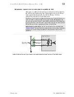
well as from the motor case. This design feature ensures that control
signals will not be compromised due to induced currents from the motor,
power supply, or other sources of common mode noise or ground loops.
I
NPUT
W
IRING
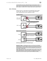
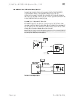
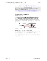
ClearPath inputs are compatible with standard digital output formats
including open collector transistor, and driven outputs from PLCs,
sensors, signal generators, microcontrollers and more.
For Step and Direction and Pulse Burst Modes
Install 1k resistor on output side as shown
for cable runs longer than 10 feet.
1k
IN
+
IN
-
Current
Limiter
+V
IN
+
IN
-
Current
Limiter
+V
IN
+
IN
-
Current
Limiter
NPN / Sinking
“Open Collector”
PNP / Sourcing
1k
IN
+
IN
-
Current
Limiter
+V
Signal
Signal
Sourcing
Sinking
Signal low = Input asserted
Signal high = Input asserted
ClearPath Input
ClearPath Input
ClearPath Input
ClearPath Input
Transistor Outputs
Driven Outputs, Single-Ended
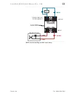
Interfacing digital outputs to ClearPath Inputs
Engineer’s Note:
5V differential outputs are not directly compatible
with ClearPath I/O because differential drivers' guaranteed output voltage
swing is typically not guaranteed to meet the ClearPath input minimum
input voltage requirements.
While differential drivers may work initially, they may fail over time as the
environment changes, i.e. the motor heats up, components age, and so
forth. This can result in erratic operation that is difficult to debug.

