background image

1

09665

-01

.2

01

9-

Gb

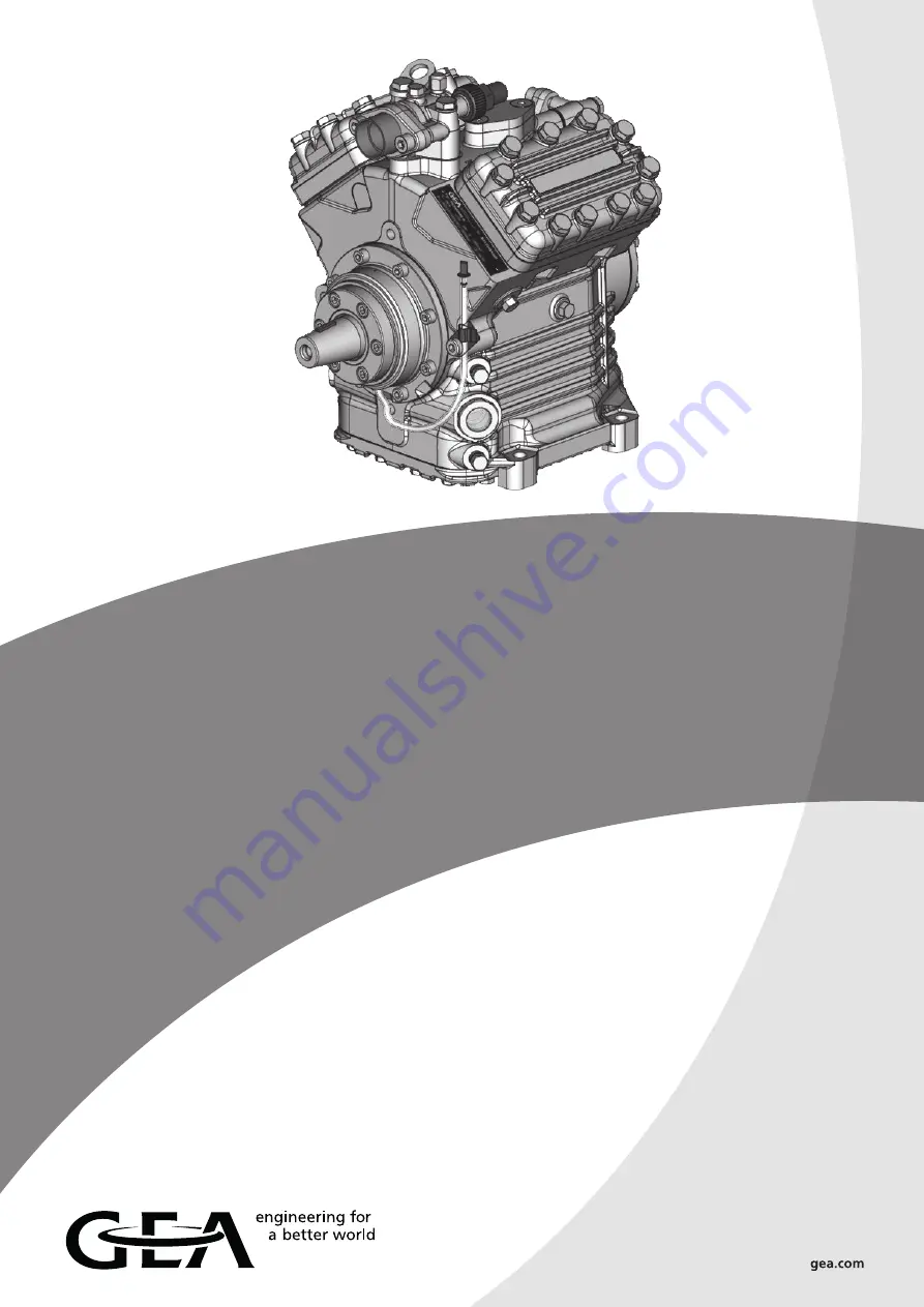
GEA Bock FK40

Maintenance manual

09665-01.2019-Gb

Translation of the original instructions

FK40/390 K 

FK40/470 K 

FK40/560 K 

FK40/655 K 

FK40/755 K 

FK40/390 N 

FK40/470 N 

FK40/560 N 

FK40/655 N 


FK40/390 TK  FK40/470 TK  FK40/560 TK  FK40/655 TK 
 
FKX40/390 K  FKX40/470 K  FKX40/560 K  FKX40/655 K  FKX40/755 K 
FKX40/390 N  FKX40/470 N  FKX40/560 N  FKX40/655 N   
FKX40/390 TK  FKX40/470 TK  FKX40/560 TK  FKX40/655 TK

Содержание FK40/390 K

Страница 1: ...ns FK40 390 K FK40 470 K FK40 560 K FK40 655 K FK40 755 K FK40 390 N FK40 470 N FK40 560 N FK40 655 N FK40 390 TK FK40 470 TK FK40 560 TK FK40 655 TK FKX40 390 K FKX40 470 K FKX40 560 K FKX40 655 K FKX40 755 K FKX40 390 N FKX40 470 N FKX40 560 N FKX40 655 N FKX40 390 TK FKX40 470 TK FKX40 560 TK FKX40 655 TK ...

Страница 2: ...erations and functional modifications have been carried out No original replacement parts have been used Contents Page 1 Introduction 3 2 Safety 3 3 Product description 5 4 Technical data 8 5 Maintenance 9 6 Fault diagnosis 11 7 Installation of service kits 15 8 Electromagnetic coupling 21 9 Compressor defects 23 10 Disassembly of the compressor 24 11 Checking the compressor parts 37 12 Assembly o...

Страница 3: ...et group of these instructions Work on the compressor may only be carried out by persons whose technical training skills and expe rience along with their knowledge of pertinent regulations and documentation means that they are capa ble of assessing the work to be carried out and detecting any possible dangers Specialist can mean a refrigeration technician for example Note that electrical work may ...

Страница 4: ... the safety switch out of action Prior to commissioning check whether all the components installed by the user have been fastened expertly and connected pressure tight with the compressor e g piping plugs union nuts replaced components etc Before commissioning evacuate the refrigerant systems carefully including the compressor and afterwards charge refrigerant Prior to starting the compressor open...

Страница 5: ...s as regards capacity Aluminium light weight construction Crankshaft supported in roller bearings on both sides Bidirectional lubricating oil pump with relief valve Variable arrangement shut off valves Ideally equipped with valve plates for each application Integrated pulsation damper for especially quiet running Name plate example 1 Type designation 4 Machine number 2 Displacement at 1450 rpm 5 F...

Страница 6: ...r 3 Valve plate 4 Compressor housing 5 Location hole for fitting magnetic coupling 6 Integrated leak oil collector 7 Leak oil drain hose 8 Shaft seal 9 Shaft end 10 Baseplate 11 Connection thermal protection thermostat 12 Oil filling plug 13 Oil sight glasses 2x 14 Oil drain plug 15 Suction line valve 16 Oil pump 17 Oil drain plug Oil filter 18 Name plate ...

Страница 7: ...aße in mm Änderungen vorbehalten Subject to change without notice Sous réserve de toutes modifications Sight glass Version K 1 0851 13983 0 Schauglas K 1 Ne possible qu ex usine L Raccord à braser 1 Only possible ex factory L Brazing connection L 1 Nur ab Werk möglich Raccord opt vanne d arrêt d aspiration Anschluß Wärmeschutzthermostat Connection thermal protection thermostat 2 x 1 1 8 18 UNEF Ra...

Страница 8: ... Oil pump FK X 40 390 4 385 33 5 34 0 22 7 8 28 1 1 8 2 0 0 0043 Forced lubrication Rotation independent FK X 40 470 466 40 5 33 0 28 1 1 8 35 1 3 8 FK X 40 560 554 48 3 33 0 28 1 1 8 35 1 3 8 FK X 40 655 650 56 6 31 0 35 1 3 8 35 1 3 8 FK X 40 755 755 65 6 31 0 35 1 3 8 35 1 3 8 Connections The technical data for the different designs K N and TK are identical The compressor type data therefore do...

Страница 9: ...perating point The oil level must be visible in the sight glass Changing oil In case of orderly manufactured and operated plants an oil change is in principle not absolutely necessary Yet based on decades long experience we recommend to carry out the following oil change and servicing First oil change at the first maintenance of the vehicle After that changing the oil every 5000 operating hours bu...

Страница 10: ...e 1 Turn 1 2 1 rotation to the right Service connection 2 opened shut off valve opened position B Fig Connection 3 is provided for safety devices and is not lockable 1 3 Pipe connection 2 5 I Maintenance Operating of the shut off valves Position A Position B INFO Before opening or closing the shut off valve loosen the valve spindle seal Fig left by 1 4 turn After operating the shut off valve tight...

Страница 11: ...lve not functioning properly Check the setting of the expansion valve Solenoid valve on the liquid line not opening Check the control function Fault diagnosis In case of malfunctions during compressor operation we recom mend to prepare a measurement record for aiding the fault search Pressure measurement Discharge side suction side oil pressure Temperature measurement Compressor casing discharge e...

Страница 12: ... switch Condensing pressure too high Check the setting of the high pressure switch Adjust the switching points or replace switch Pressure valve of the compressor closed Open the pressure valve Condenser fan not functioning Check the control replace motor Condenser performance insufficient con denser and fan motor contaminated Cleaning of condenser fins and fan Excessive refrigerant filling Extract...

Страница 13: ...change Valve plate damage Replace valve plate Internal decompression valve has opened Replace decompression valve see the section on Disassembly Assembly of Compressor Oil problems Problem Possible cause Remedy Oil pressure too low Refrigerant in oil see Oil foams Too little oil in compressor Add oil and search for the cause of oil loss Oil filter dirty blocked Clean replace oil filter Change oil ...

Страница 14: ...omagnetic coupling slipping see also p 14 Malfunction of electromag netic coupling Checking V belt drive increased noise generation Belts vibrating excessively Check belt tension Use tensioning roller guidance roller Incorrect alignment of compressor and motor Check alignment and adjust anew Malfunction of the electromagnetic coupling Problem Possible cause Remedy Coupling not switching No voltage...

Страница 15: ...identical WARNING Before starting any work on the compressor Switch of the compressor and guard it against switching on Close the discharge and suction shut off valves Relieve the compressor from system pressure Prevent air from infiltrating the system Move and transport the compressor using an appropriate hoist Use only genuine GEA Bock spare parts After the work is finished Connect the safety sw...

Страница 16: ... 4 O ring 3 and the guide ring 2 together as a unit The large chamfer on the sliding ring 4 should show in the direction of the shaft seal cover 6 During the assembly the compression spring 1 must engage audibly in the drive slot of the crankshaft and of the guide ring 2 Install the shaft seal cover gasket 5 with applied compressor oil Install the shaft seal cover 6 with the inscription TOP upward...

Страница 17: ...n be emptied very simply without having to dismantle the coupling and or belt drive It is recommended that this is done at the same time as the air conditioning maintenance and motor service Proceed by removing the oil hose from the bracket remove the sealing plug and drain the oil into a collecting vessel After emptying close the oil hose with the sealing plug and fix it to the bracket Dispose of...

Страница 18: ...er bank which is regulated down run idle The capacity of the compressor is still approx 50 Further information together the description of the working principle of the solenoid valve is contained in the publication Capacity regulation Item No 09900 Capacity regulation valve Item No 07541 Removal De energize the solenoid 4 Screw on the fixing nut 3 pull out the solenoid 4 with the washer 5 Unscrew ...

Страница 19: ...essor type Kit Item No FK X 40 390 N 80240 FK X 40 390 TK 80240 FK X 40 470 N 80240 FK X 40 470 TK 80240 FK X 40 560 N 80241 FK X 40 560 TK 80241 FK X 40 655 N 80241 FK X 40 655 TK 80241 FK X 40 390 K to FK X 40 655 K 80010 FK X 40 755 K 81297 K type valve plate N type and TK type Valve plate Fig 6 ...

Страница 20: ...Pay attention to the correct installation position of the gaskets 3 5 of the valve plate 4 and of the cylinder cover 2 Tighten the cylinder cover screws Pos 1 in Fig 6 according to the sequence shown in Fig 7 Fig 7 Sequence for tightening the cylinder cover screws 9 11 10 8 5 1 4 6 3 2 7 ATTENTION The conversion of the compressor from one type of valve plate to another is not possible INFO Don t l...

Страница 21: ...A 16 The front bearing flange has a location face Ø 148 h8 for fitting the solenoid of the electromagnetic coupling see Fig 8 Fig 8 Front bearing flange Magnetic field Fig 9 148 h8 For fitting the solenoid 1 remove the four M8x25 cylinder screws 2 on the bearing flange indicated with circles and arrows Fig 8 page 21 and Fig 10 page 22 Fit the solenoid onto the location seat and fasten it again wit...

Страница 22: ...n it Screw tightening torque 85 Nm Install the K circlip 5 Push the sheave 6 over the studs 9 and fasten it with zinc coated M8 DIN 934 8 nuts 7 Connect the cable 8 The connection is polarity independent Voltage 10 of nominal voltage Fig 10 ATTENTION With all other methods of removal pressing hammering there is risk of damage to the coupling INFO Arrange the cable 8 so that it doesn t touch hot pa...

Страница 23: ...ean the system install a suction line filter if necessary Moisture in the system Dry the system trough changing refrigerant and oil replace the drier install a suction line filter if necessary Overheating of compressor Heat protection thermostat switches off Check the operating conditions Overloading of compressor Compare the operating conditions with the application limits Pistons Connecting rods...

Страница 24: ...ystem Close the suction and discharge shut off ports on the compressor with stoppers Disassembly of compressor The disassembly of the compressor is explained in separate steps on the following pages The indicated parts list positions refer to the spare parts lists repair set lists special accessories part lists and are available online at www gea com You can find the exploded drawing at the end of...

Страница 25: ...17 allen key 6 mm Working course 220 330 210 230 210 233 232 231 The compressor has to be depressurized Unscrew the fixing screws of shut off valves Remove the shut off valves and the gaskets Remove the suction filter and the gasket Remove the screws from the blind flange Remove the blind flange and the O ring 10 I Disassembly of the compressor ...

Страница 26: ...il filter Position in parts list Parts list position 2130 Tools Container 2 liter for collection oil spanner SW 19 allen key 10 mm Working course 510 500 490 Drain the oil from the compressor into a suitable container Unscrew the plug Remove the gasket Unscrew the oil filter ...

Страница 27: ... Removal of the cylinder cover and valve plates Position in parts list N TK K Parts list position 170 2000 N TK versions 1940 2900 K version Tools Spanner SW 17 Working course 180 181 170 70 60 50 1950 180 1940 1430 1920 1910 Loosen screws at the cylinder cover and unscrew remove the washers Remove the cylinder cover and the upper gasket of the valve plate Remove the valve plate and the lower gask...

Страница 28: ... Remove the leak oil collection device from the bearing flange until version ID 014 Unscrew the cylinder screws Remove the shaft seal cover the guide ring the O ring and the spring INFO For a detailed description for the old version until version ID 014 see also the section on the removal of the shaft seal on page 16 CAUTION Danger of injury The shaft seal cover is under spring tension It may jump...

Страница 29: ...moval of the oil pump Position in parts list Parts list position 2020 Tools Spanner SW 13 Working course 40 41 460 470 Loosen screws on the oil pump and unscrew Remove the oil pump and gasket 10 I Disassembly of the compressor ...

Страница 30: ...seplate Position in parts list Parts list position 20 30 40 Tools Container for collection oil spanner SW 13 Working course 40 20 30 Place the compressor into the oil collection pan and turn it sideways Unscrew the screws from the baseplate Remove the baseplate and the gasket ...

Страница 31: ...se 2100 2100 2040 2045 300 290 Unscrew the hexagon head screws from the connecting rod cap Mark the connecting rod cap and remove it Push the piston and connecting rod upwards until the stop Remove the piston rings The same procedure should be applied for the remaining connecting rods INFO In order to prevent any mix up during reassembly mark the connecting rods and caps belonging together clearly...

Страница 32: ... bearing Position in parts list Parts list position 2140 Tools Allen key 6 mm Working course 750 730 740 745 Loosen the screws at the front bearing and unscrew Remove the front bearing flange gasket and O ring 10 I Disassembly of the compressor ...

Страница 33: ...9 Gb 9 Removal of the crankshaft Position in parts list Parts list position 2050 Tools Working course 2050 Pull out the crankshaft carefully in direction of the front bearing flange 10 I Disassembly of the compressor ...

Страница 34: ...h 2100 Tools Needle nosed pliers Working course 2100 2030 280 270 2100 Mark corresponding pistons of cylinder bore Remove the piston connecting rod in direction of baseplate Remove circlips of the piston pins with needle nosed pliers Push the piston pins out of the pistons and remove pistons In order to prevent mix ups fasten the connecting rod caps to the connecting rods again ...

Страница 35: ...or 36 For the decompression valve GEA Bock special tool item No 09524 up to A015 socket wrench SW 22 from A017 Working course 570 590 520 521 100 Dismount the sight glass Remove O ring Remove the 1 8 NPTF plugs Remove the 1 4 NPTF plugs Unscrew the decompression valve 520 521 521 570 590 2080 100 see the last four sites of the machine number 590 570 2080 520 ...

Страница 36: ...er bearing from the front bearing flange If a pulling apparatus is not available the front bearing flange may be heated for approx 15 minutes in a pre heated 220 C baking oven Afterwards the roller bearing can be pressed out by hand Press out the roller bearing from the compressor body Take out the tolerance ring if there is any INFO Use oil if necessary CAUTION Risk of burns Parts are hot Use pro...

Страница 37: ...o that an unhindered oil flow is ensured Piston cylinder bore 0 13 mm Connecting rod piston pin 0 03 mm Crankshaft connecting rod 0 08 mm Checking compressor parts for damages and wear Before re using removed compressor parts we recommend that they be checked for usability The wear limits listed below should be taken into consideration 1 2 3 1 2 3 Clean the oil channels with compressed air and che...

Страница 38: ... The connecting rod shank must be straight Valve plates Suction and pressure lamella must be undamaged and undeformed The sealing surfaces must be clean and undamaged between lamellas and valve plates there should not be any pollution dirt swarfs etc In case of a damage the valve plate must be replaced completely Single lamella are not available Oil pump It must be possible to turn the oil pump by...

Страница 39: ...e use GEA Bock special tool item No 09524 up to A015 socket wrench SW 22 from A017 The internal decompression valve must be replaced after it has operated INFO In case of larger compressor damages which necessitate a complete disassembly of the compressor we recommend in principle the replacement of the following assemblies Valve plates Piston rings Shaft seals Roller bearings Thus concealed defec...

Страница 40: ... 730 312 2150 Heat the bearing flange compressor casing for approx 20 minutes in a pre heated 120 C baking oven Insert tolerance ring into the roller bearing if available Press the roller bearings onto the compressor casing and the front bearing flange CAUTION Risk of burns Parts are hot Use protective gloves INFO Use tolerance ring if the bearing seat has a groove ...

Страница 41: ... Bock special tool item No 09524 up to A015 socket wrench SW 22 from A017 Working course 570 590 520 521 100 Screw on the sight glass with oiled O ring to the compressor body Screw in the 1 8 NPTF screw plugs Screw in the 1 4 NPTF screw plugs Screw in the decompression valve into the suction channel 20 Nm 20 Nm 25 Nm INFO Observe the screw tightening torques 520 521 521 570 590 2080 100 590 570 20...

Страница 42: ...ds Position in parts list Parts list position 2040 opt 2045 or 2030 opt 2035 together with 2100 Tools Needle nosed pliers Working course 270 280 Assemble piston and connecting rod with piston pin use some oil for easier assembly Mount circlips with pliers on both sides of the piston pins ...

Страница 43: ...reassembled connecting rod assembly and mark it Apply a little oil to the cylinder bore Insert pistons connecting rods from below into the cylinder liners In the case of TK compressors pay attention to the correct assembly position of the pistons suction fin grooves see figure Install oil scraper rings in the lower groove and compression rings in the upper groove Fit with the marking TOP facing up...

Страница 44: ... Assembly of compressor 5 Fitting the crankshaft Position in parts list Parts list position 2050 Tools Working course 2050 Fit the crankshaft so that the drive journal engages into the pump gear Apply bearing position with oil ...

Страница 45: ...0 730 740 750 Apply oil to the O ring and place it into the groove in the bearing flange The sealing surfaces have to be clean Slightly oil seals Install the front bearing flange with gasket to the body so that the hole for the clamping ring faces upwards Tighten the screws M8x25 crosswise 12 I Assembly of compressor 34 Nm INFO Observe the tightening torques ...

Страница 46: ...ton into the cylinder liner Place the marked connecting rod caps onto the related connecting rods Screw on the connecting rod caps and tighten Turn the crankshaft by hand In case the crankshaft does not rotate freely check the seating of the connecting rods if necessary disassemble the connecting rods and carry out this step once more 12 I Assembly of compressor INFO Pay attention to the correct p...

Страница 47: ...ust axial clearance The axial clearance of the crankshaft must be at least 0 15 mm When parts of the driving unit of the compressor have been repaired or replaced an accurate measurement of the axial clearance is neces sary The measurement has to be at the disassembly shaft seal cover If the axial clearance is less than 0 15 mm the bearing flange must be disassembled and a second seal must inserte...

Страница 48: ... gasket using the protective sleeve The inscription TOP must be at the top Press the shaft seal cover onto the bearing flange and tighten the screws Turn the crankshaft by hand Remove the protective sleeve Install the leak oil collection device only up to version ID 014 and see also under service kits clamping ring with oil felt 12 I Assembly of compressor INFO Caution Avoid damages Pay attention ...

Страница 49: ...49 09665 01 2019 Gb POE TOP TOP TOP 2 3 4 5 6 mm 8 9 POE 1 2 3 4 5 6 TOP TOP 6 7 CLICK 2 4 6 5 3 7 9 Fitting the shaft seal ...

Страница 50: ...50 09665 01 2019 Gb 8 9 1 2 3 4 5 6 TOP 10 11 12 6 mm 37 Nm 8 10 9 9 Fitting the shaft seal ...

Страница 51: ...parts list Parts list position 20 30 40 Tools Spanner SW 13 Working course 20 30 40 Install the baseplate with gasket Tighten the screws M8x30 crosswise 11 14 18 15 12 13 17 16 10 4 2 6 3 9 5 1 7 8 34 Nm INFO Observe the tightening torques Pay attention to the tightening sequence of the screws ...

Страница 52: ...t position 2130 Tools Allen key 10 mm spanner SW 19 Working course 490 500 510 With the allen key screw on the filter into the hole in the body and tighten it Install gasket Screw on the M22x1 5 mm plug and tighten it 12 I Assembly of compressor 100 Nm INFO Observe the tightening torques ...

Страница 53: ...unt the valve plate with the lower valve plate gasket onto the body Mount the cylinder cover with the upper valve plate gasket on the valve plate Tighten the screws and washers cross wise in at least two steps 12 I Assembly of compressor ATTENTION Install only the cylinder covers and valve plates which belong together avoid mix ups Observe the tightening torques 60 Nm INFO Mount the K type plate w...

Страница 54: ...urse 230 210 2060 233 232 231 Put in the suction filter with the gasket Install the shut off valves on the discharge and suction side with gaskets and screws Install the blind flange with O ring and screws Tighten all screws 12 I Assembly of compressor INFO Observe tightening torques Use screws of correct length for the installation of the intermediate flanges 60 Nm 60 Nm 60 Nm ...

Страница 55: ...gn Note Tighten the screws cross wise in at least two stages tightening torque 50 100 Working course 1 Evacuation leak check of compressor Connect the discharge and suction sides of the compressor to a vacuum pump Evacuate the compressor from both sides vacuum 1 5 mbar Check increase in pressure In case there is an increase in pressure check the compressor for leaks and evacuate again Fill in the ...

Страница 56: ... N K TK 2 05075 05075 05075 05075 05075 270 Piston pin Ø 15x10x41 N K TK 4 07211 270 Piston pin Ø 15x10x46 N K TK 4 07212 07212 270 Piston pin Ø 15x10x50 N K TK 4 07857 07857 280 Seeger circlip 15x1 DIN 472 N K TK 8 05551 05551 05551 05551 05551 290 Oil scraper ring piston 50 N K TK 4 05389 290 Oil scraper ring piston 55 N K TK 4 05390 290 Oil scraper ring piston 60 N K TK 4 06562 290 Oil scraper ...

Страница 57: ...6 06726 06726 740 Front bearing flange gasket N K TK 1 06165 06165 06165 06165 06165 745 O Ring Ø 101 19x3 53 N K TK 1 05169 05169 05169 05169 05169 750 Cylinder screw M8x25 N K TK 14 06067 06067 06067 06067 06067 790 Woodruff key A5x9 DIN 6888 N K TK 1 05673 05673 05673 05673 05673 800 Disc Ø 50x12 5x8 N K TK 1 04425 04425 04425 04425 04425 2 810 Spring washer B12 N K TK 1 05666 05666 05666 05666...

Страница 58: ...49 2045 Set piston con rod Ø 55 rilled optimized TK 4 80250 2045 Set piston con rod Ø 60 rilled optimized TK 4 80251 2045 Set piston con rod Ø 65 rilled optimized TK 4 80226 2050 Set crankshaft 49 stroke optimized N K TK 1 80154 80154 80154 80154 80154 2060 Set shut off valve NW25 AL N K TK 1 08084 2060 Set shut off valve NW32 AL N K TK 1 08082 08082 08082 08082 2 2070 Set shut off valve NW20 AL N...

Страница 59: ...een N K TK 1 05987 05987 05987 05987 05987 3312 Disc Ø30x16x2 0 N K TK 1 05143 05143 05143 05143 05143 3313 Milled nut M15x1 with O Ring N K TK 1 05885 05885 05885 05885 05885 3320 Solenoid coil 24V DC N K TK 1 07526 07526 07526 07526 07526 3600 Set replacement adapter set the same shut off valve positioning similar to FK4 467 not shown N K TK 1 80022 80022 80022 80022 80022 3800 Set capacity regu...

Страница 60: ...70 2035 2100 2045 280 FK40 390 655 N TK 3313 3312 3311 3310 3320 3250 3220 3240 3200 3300 181 FK40 390 755 K 3313 3312 3311 3320 3300 3850 3820 3840 3800 3310 181 1930 1920 1910 2900 FK40 390 755 K 1950 181 1940 Zubehör Accessories Stand As of date 07 16 0i Fahrzeugverdichter Vehicle Compressor Typ type Teile Nr part no Typ type Teile Nr part no Typ type Teile Nr part no FK X 40 390 N 13977 13985 ...

Страница 61: ...61 09665 01 2019 Gb ...

Страница 62: ...geration gea com www gea com GEA Group is a global engineering company with multi billion euro sales and operations in more than 50 countries Founded in 1881 the company is one of the largest providers of innovative equipment and process technology GEA Group is listed in the STOXX Europe 600 index We live our values Excellence Passion Integrity Responsibility GEA versity ...

Отзывы: