C
L E A R
P
A T H
M C / S D
U
S E R
M
A N U A L
R
E V
.
3 . 0 9
8 4
T
EKNIC
,
I
NC
. T
EL
.
(585)
784-7454
5
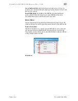
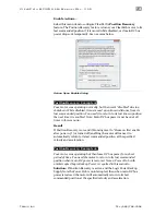
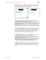
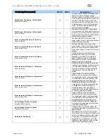
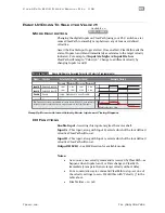
Filter
“cleans up” the appearance of the live trace by removing higher
frequency data content. This has an averaging effect on the displayed
waveform that will generally reduce visual clutter.
Effect of Scope Filter on trace display
Note:
The Scope Filter has no effect on motor performance.
It only
changes the appearance of displayed scope data.
Note:
Be careful! A high filter setting may filter out meaningful data (fast
peaks in particular).
Tip:
In most cases Scope Filter can be left “OFF” or at the lowest setting.
6
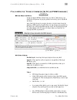
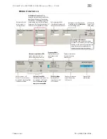
Trace Storage controls
allow you to save and display one trace per
channel on the scope display. Just capture a waveform and click either the
"Store A" or "Store B" button. The selected trace is then stored and
displayed in either pink (Store A) or blue (Store B). Hide or show either
stored trace by clicking its associated Show/Hide button.
7
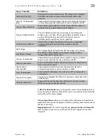
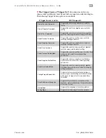
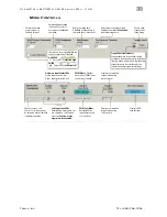
The Trigger Level
lets you select the amplitude (of the variable you
are currently measuring) at which the scope will trigger.
Note:
Trigger Level can only be used when Trigger Source is set to
“Rising Slope” or “Falling Slope”.
Tip:
Use Trigger Level when the Trigger Mode is set to “Normal” or
“Single” to facilitate waveform display at a fixed trigger point.
8
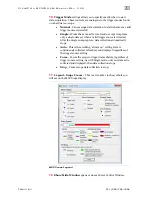
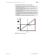
Trigger Position
buttons allow you to place the trigger point on the
left, middle, or right side of the scope display grid. This is useful for
viewing events on the scope that occur before, during, or after the trigger
event.

