


39
Power Supply and Connectors
Cha
pt
er 2
Name
s an
d F
unc
tions
of
P
ar
ts
5
Enter the page number for the menu you want to
register.
To register the currently displayed menu
1
In the Home >Favorites >Shortcut menu (0021), select
the group to which you want to register the menu
beforehand.
2
Display the menu you want to register in the shortcut
menu.
3
Press the menu page number button, and press [Add
Favorite].
The menu selected in step
2
is automatically registered
to an open button in the group selected in step
1
.
Customizing the shortcut menu
To customize buttons
1
In the Home >Favorites >Shortcut menu (0021), press
[Button Edit].
The Home >Favorites >Button Edit menu (0023)
appears.
2
Use the following procedures.
To rename the button
Select the button you want to change, press [Rename],
enter a new button name (up to 24 characters), and
then press [Enter].
To change the button color
Select the button you want to change, press [Color
Set], and then select the desired color.
To copy button settings
Select the button you want to copy, press [Copy], and
then select the target button and press [Paste].
To delete button settings
Select the button you want to delete, then press
[Clear].
To customize groups
1
In the Home >Favorites >Shortcut menu (0021), press
[Group Edit].
The Home >Favorites >Group Edit menu (0022)
appears.
2
Use the following procedures.
To rename a group
Select the group you want to change, press [Rename],
enter a new group name (up to 24 characters), and then
press [Enter].
To copy group settings
Select the group you want to copy and press [Copy],
and then select the target group and press [Paste].
To delete group settings
Select the group button you want to delete, press
[Clear]. Check the message, then press [Yes].
Power Supply and Connectors
MVS-3000 Multi Format Switcher Processor
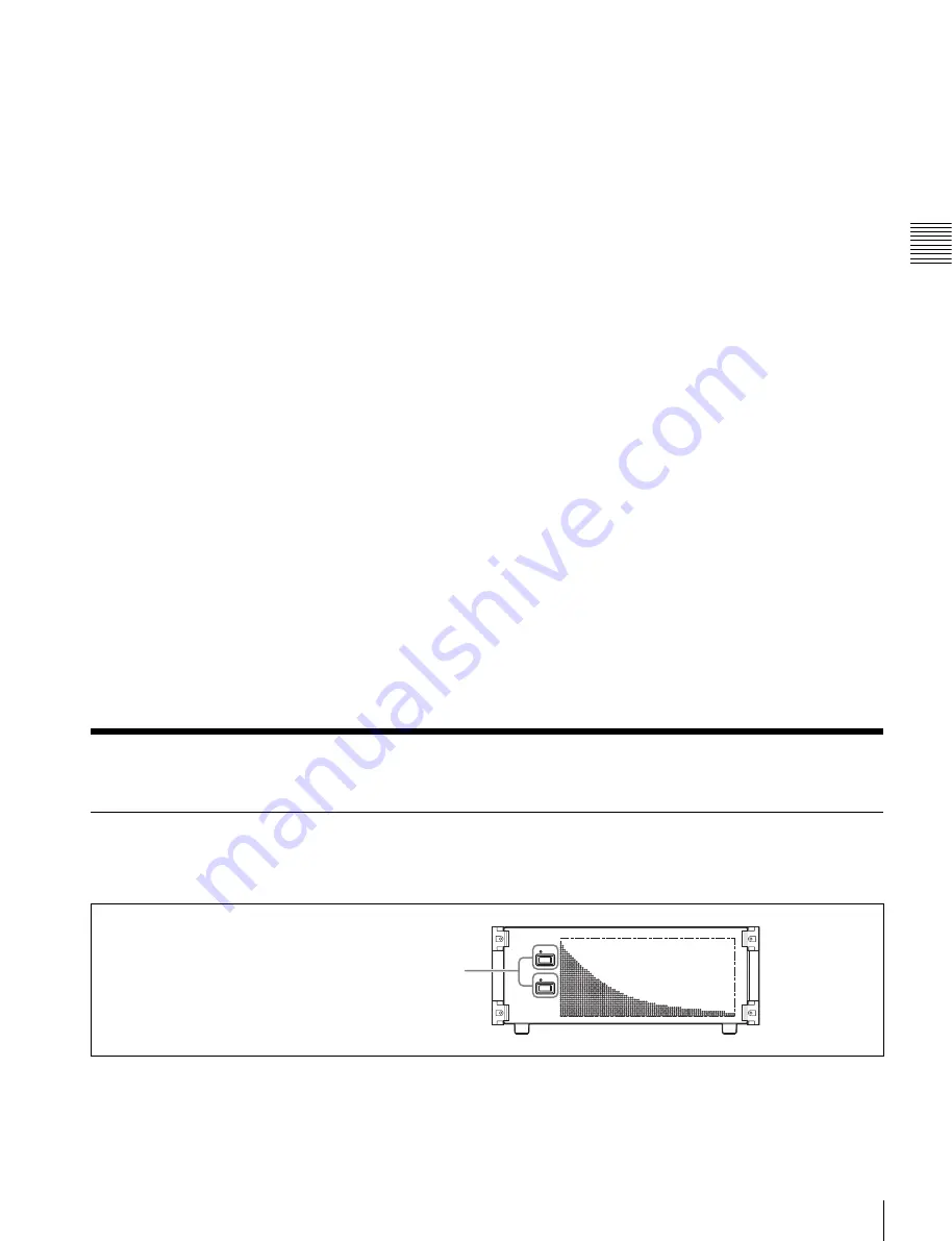
Front panel
POWER A, B switches and status indicators
The POWER switches turn the unit on and off. The unit is
powered on when the POWER switches are on the “
?
”
side, and powered off when the POWER switches are on
the “
a
” side. The status indicators light in green when the
unit is powered on.
Operation continues as long as power supply is normal on
one unit.
POWER A, B switches and status indicators


