3 Safety-Related Functions
11.03
3.1 Basic mechanisms of SI functions
© Siemens AG 2003 All Rights Reserved
3-68
SINUMERIK 840D/SIMODRIVE 611 digital SINUMERIK Safety Integrated (FBSI) - Edition 11.03
Table 3-3
Overview of stop responses
STOP Action
Effect
Initiated
in
response to
Changes
to
Alarm
A
Pulses are immediately cancelled Drive coasts to standstill
SBR/SG
SH
POWER ON
B
0 speed setpoint is immediately
entered
+ start timer t
B
t
B
=0 or n
act
<
n
shutdown
: STOP A
Drive is braked along
current limit
transition to STOP A
SBH/SG SH
POWER
ON
C
0 speed setpoint is immediately
entered
+ start timer t
C
t
C
=0:
Activation of SBH
Drive is braked along
current limit
SBH active
SG/SE SBH RESET
D
Brake motor along acceleration
limit
+ start timer t
D
t
D
=0:
Activation of SBH
Drive is braked as part of a
group along set traversing
path
SBH active
SG/SE SBH RESET
E
Causes stop and retract
+ start timer t
D
t
D
=0:
Activation of SBH
Drive is decelerated via the
programmed retraction and
stop motion (ESR).
SBH active
SG/SE SBH RESET
F
Depending on situation:
a) Safety function inactive:
Saved message to operator
a) NC start and traversing
interlock
a)
RESET
b) Safety function active:
Initiation of STOP B/A
(configurable)
b) Transition to STOP B/A
Crosswise
data
comparison
SH b)
POWER
ON
c) Safety function active and
initiation of STOP C, D or E:
Saved message to operator
c) NC start and traversing
interlock
c)
RESET
Note:
The timers can be set using the machine data.
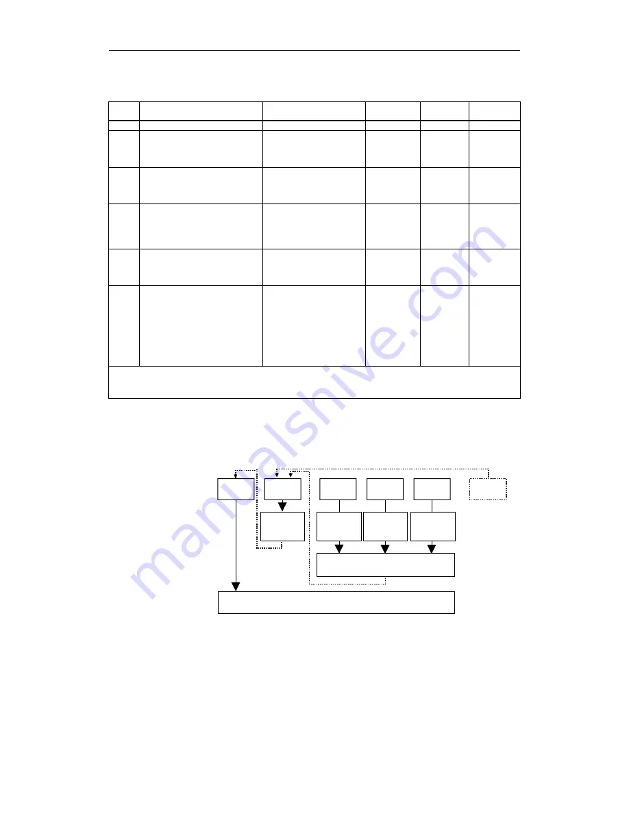
The following diagram shows the relationship between the stop responses and
the safe operating stop (SBH) or the safe standstill (SH).
Stop
Input
setpoint "0"
STOP A
STOP B
STOP C
STOP D
STOP E
STOP F
Stop
Path-relating
in grouping
Stop
Input
setpoint "0"
Stop
SBH
(Safe standstill under position control)
SH
(Safe pulse disable)
STOPR_02.DSF
(if a further error occurs)
Retraction
conditions
Fig. 3-7
Stop responses, safe operating stop (SBH), safe standstill (SH)
Stop responses SBH
and SH


