3 Safety-Related Functions
11.03
3.9 Safety-related input/output signals (SGE/SGA)
© Siemens AG 2003 All Rights Reserved
3-130
SINUMERIK 840D/SIMODRIVE 611 digital SINUMERIK Safety Integrated (FBSI) - Edition 11.03
SBH/SG
SE
SN
SGEs
SGAs
SBH/SG deselection
SBH deselection
SG selection, bit 1
SG selection, bit 0
SE selection
Gear ratio selection, bit 2
Gear ratio selection, bit 1
Gear ratio selection, bit 0
Test stop selection
Pulses disabled status (NCK)
SG correction selection bit 3
1)
SG correction selection bit 2
1)
SG correction selection bit 1
1)
SG correction selection bit 0
1)
ext. STOP A deselection
2)
ext. STOP C deselection
2)
ext. STOP D deselection
2)
SBH/SG active
Axis safely referenced
SN1 -
SN2 -
SN3 -
SN4 -
SN1 +
SN3 +
SN2 +
SN4 +
n < n
x
1)
SG active bit 1
1)
SG active bit 0
1)
SBH active
1)
Enable pulses (NCK) or
Pulses are disabled status (drive)
1)
840D from SW4.2
2)
840D from SW 4.4.18
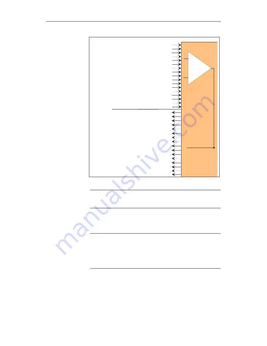
Fig. 3-29
SGEs and SGAs in each monitoring channel for each axis/spindle
Note
The SGE/SGA signals are described in Chapter 4, "Description of Interface
Signals".
Only a subset of the maximum number of available SGEs/SGAs is required
depending on the application.
Note
SGEs that are not needed must be set to a defined signal status.
In the NCK monitoring channel:
By presetting the assigned machine data to appropriate values
(e.g. input is permanently set to 0 (default) or 1)
In the drive monitoring channel:
By appropriately programming the interface signals in the PLC user program.
What is the minimum
number of SGEs/SGAs
that are needed?


