8 Application examples
11.03
8.4 Safe cams at the modulo limit
© Siemens AG 2003 All Rights Reserved
8-458
SINUMERIK 840D/SIMODRIVE 611 digital SINUMERIK Safety Integrated (FBSI) - Edition 11.03
SN1-
89.5°
0°
90.5°
Modulo
correction
SN1-
Position detection
90 degrees
&
SN1+
SN1+
inverted
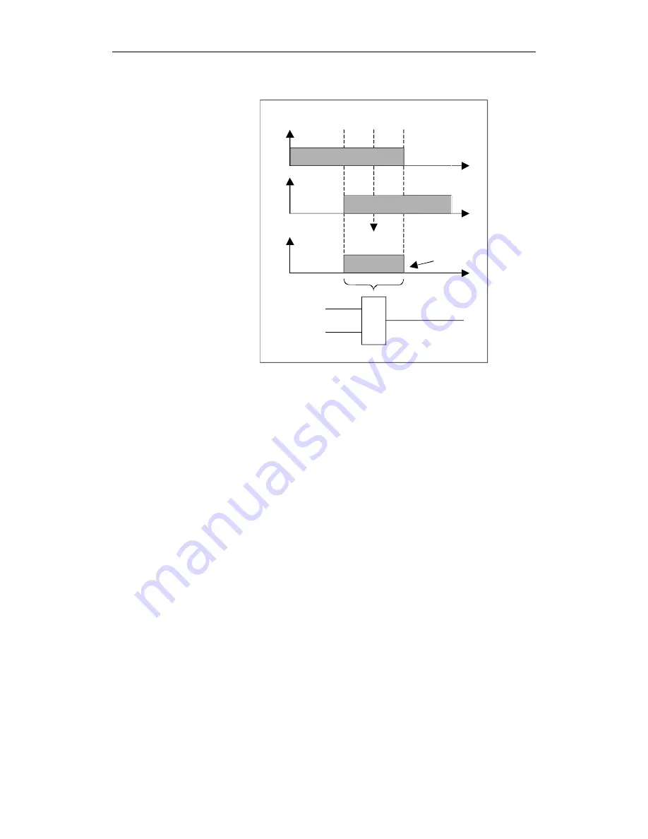
Fig. 8-8
Negating a safe cam signal to generate a pulse
The appropriate machine data settings are used to negate SN1+ and round-off
on the NCK side. To implement this, the two cam signals should be
parameterized to an NCK output
36988
SAFE_CAM_PLUS_OUTPUT[0]
81040101
36989 SAFE_CAM_MINUS_OUTPUT[0]
01040101
or a system variable ($A_INSI[1])
36988
SAFE_CAM_PLUS_OUTPUT[0]
84010101
36989
SAFE_CAM_MINUS_OUTPUT[0]
04010101
The minimum logic (Chapter 3.9.19) of the NCK safety channel is used for
multiple assignment to an output or a system variable. This includes the
rounding-off of the assigned signals.
This type of logic is not available in the form of parameter settings on the
PLC side. The negation on the NC side is not effective for the drive (PLC) side,
therefore the position detection has to be programmed as shown below:
UN DB3x.DBX109.0
//
SN1+
U DB3x.DBX109.1
//
SN1-
=
M1.0
// Position detection 90° in
//
marker
1.0
= DB18.DBX54.0
// $A_INSIP[1]
//
Position
detection
90°
At the modulo limit, the cams respond differently to the description in 1)
because of the modulo correction.
The following positions are saved in the machine data:
36936 SAFE_CAM_POS_PLUS[0] : 0.5 Degrees
36937 SAFE_CAM_POS_MINUS[0] : 359.5 Degrees
36905 SAFE_MODULO_RANGE :
360 Degrees
Position detection at
modulo limit with and
without SPL


