3 Safety-Related Functions
11.03
3.9 Safety-related input/output signals (SGE/SGA)
© Siemens AG 2003 All Rights Reserved
3-134
SINUMERIK 840D/SIMODRIVE 611 digital SINUMERIK Safety Integrated (FBSI) - Edition 11.03
Monitoring
comparators
SGESGA06.DSF
for axis 1
for axis 2
for axis 3
Inversion
...
...
...
yes / no
...
...
...
NCK
HW
...
...
...
...
...
Ox
On
Multiple
assignment
SGA
SGA
SGA
...
...
...
...
...
...
...
...
...
&
O2
O1
yes / no
yes / no
...
NCK
SGE/SGA
interface
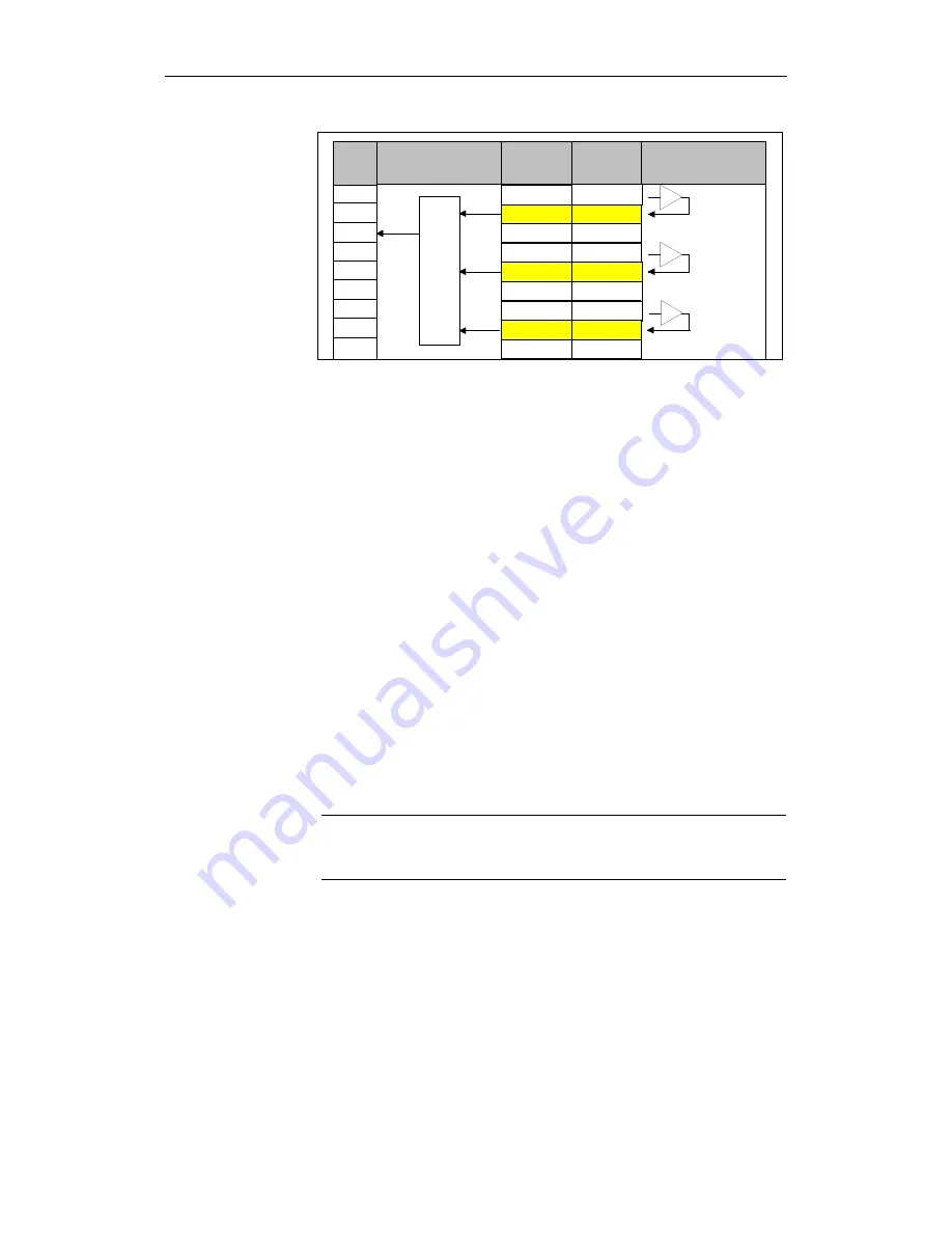
Fig. 3-31
Multiple assignment for NCK outputs
Axes 1, 2 and 3 belong to one safety zone. For these axes, the message "axes
safely referenced" must be output at one NCK output (i.e. the message is
output if the message is active for all 3 axes).
The machine data must be parameterized as follows:
Axis 1: MD 36987: $MA_SAFE_REFP_STATUS_OUTPUT = output x
Axis 2: MD 36987: $MA_SAFE_REFP_STATUS_OUTPUT = output x
Axis 3: MD 36987: $MA_SAFE_REFP_STATUS_OUTPUT = output x
(output x = ss mm xx nn, refer to Chapter 4, "Machine data for SINUMERIK
840D")
3.9.2
Signal processing in the drive monitoring channel
The safety-relevant input and output signals (SGEs and SGAs) are signals that
are sent to and received from the system via two channels:
Via the NCK monitoring channel
<--> NCK I/O devices <--> signal processing <-->
NCK SGE/SGA interface <-> NCK-CPU
Via the drive monitoring channel
<--> PLC I/O devices <--> signal processing via PLC <-->
NC/PLC
interface
<-->drive
CPU
Note
The SGEs/SGAs must be supplied by the machine manufacturer in both the
drive monitoring channel and the NCK monitoring channel.
Digital PLC inputs and outputs are implemented on the SINUMERIK 840D
using SIMATIC S7-300 I/O devices.
References:
/S7H/, SIMATIC S7-300
Example
General
Digital PLC inputs/
outputs for 840D


