11.03
7 Configuring example
7.2 Circuit examples
© Siemens AG 2003 All Rights Reserved
SINUMERIK 840D/SIMODRIVE 611 digital SINUMERIK Safety Integrated (FBSI) - Edition 11.03
7-361
If SPL is used, emulation of S7 logic by the contactors and therefore the wiring
is no longer necessary. The safe programmable logic is programmed on the
PLC side in the form of an S7 program and on the NCK side by an ASUB. A
contactless EMERGENCY STOP function can be implemented with the
external stop function and the SPL. This means that safety switching devices
are not required for the EMERGENCY STOP function. The door switch can
also be monitored by the SPL – in this case, the safety switching devices are
also not required.
7.2 Circuit examples
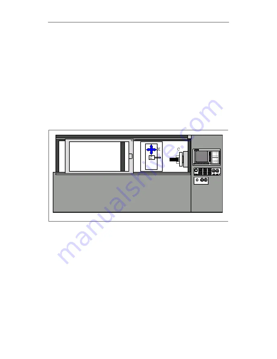
A machine tool with two axes and one spindle was selected as an example:
MASCHINE.DSF
Fig. 7-1
Schematic diagram of a machine
The following must be taken into account before the machine is configured:
•
What is the magnitude of the hazard potential?
•
Which measures can be implemented to reduce the risk?
•
What risks remain?
•
Which safety functions should be implemented?
The circuit shown below is an example of a drive with an incremental
measuring system. It is provided to illustrate the principle of how a safety zone
on a machine can be monitored.
The following functions are implemented with Safety Integrated in the example:
•
Contactless EMERGENCY STOP
Safety Integrated with
SPL and contactless
EMERGENCY STOP
General


