4 Data Descriptions
11.03
4.3 Interface signals
© Siemens AG 2003 All Rights Reserved
4-262
SINUMERIK 840D/SIMODRIVE 611 digital SINUMERIK Safety Integrated (FBSI) - Edition 11.03
n
n
x
t
N_KL_NX.DSF
SGA "n < n
x
"
0
1
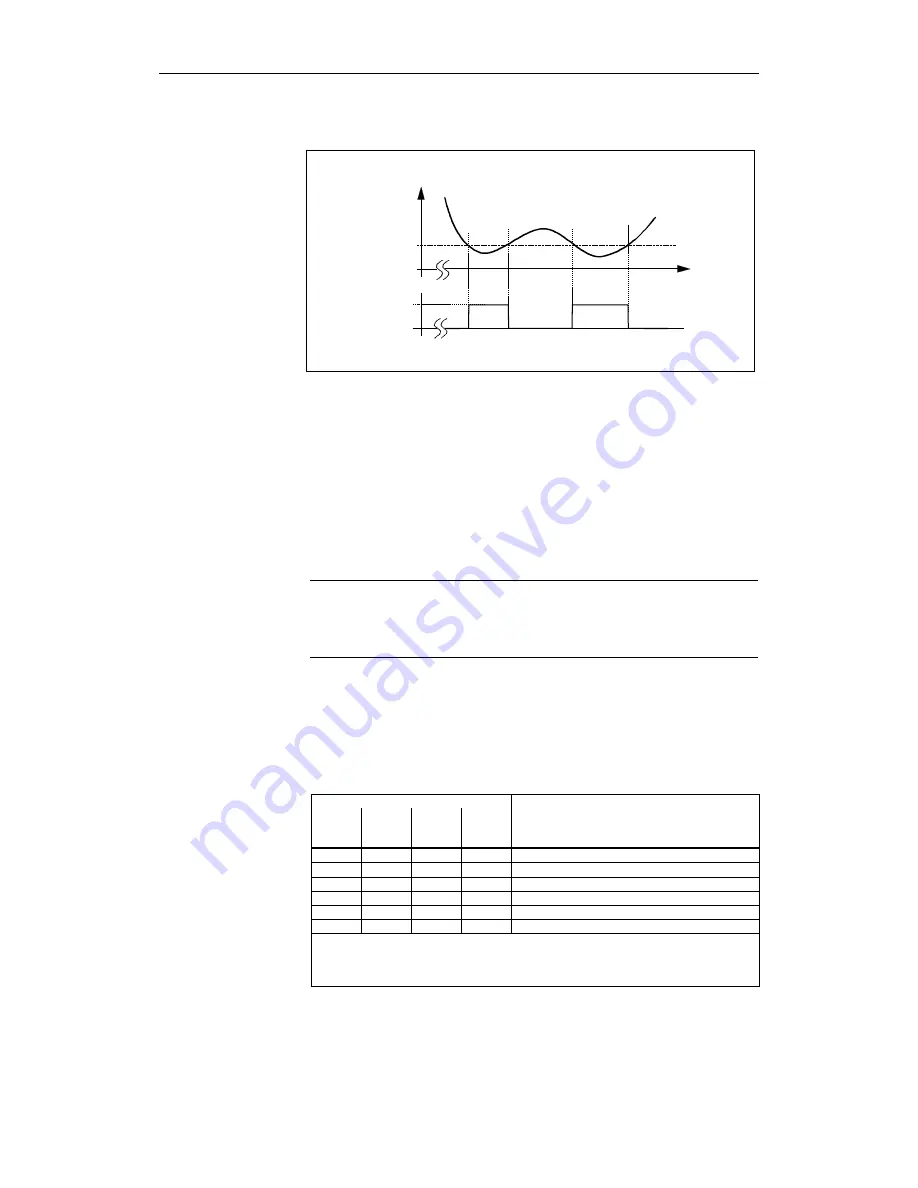
Fig. 4-2
Signal n < n
x
, depending on the speed characteristic
Only when the spindle has stopped (SGA "n < n
x
" = 0) is the chuck, for
example, controlled.
The limit speed n
x
is defined using the following machine data:
For 840D
MD 36946: $MA_SAFE_VELO_X
For 611 digital
MD 1346: $MD_SAFE_VELO_X
Note
If the axis/spindle runs at n
x,
changes in the actual value in both monitoring
channels of the SGA can cause the SGA "n < n
x
" to have different states.
This must be taken into account in the safe further processing of the SGA.
The SGAs "SG active bit 1, 0" display which safely reduced speed and
therefore which speed limit value is actively monitored. The SGAs are only
updated when the function "SBH/SG" is enabled and SG is active (SGE
"SBH/SG de-selection" = 0 and "SBH de-selection" = 1).
Table 4-7
Display of the active safely-reduced speed
SGA
SG
active
Bit 1
SG
active
Bit 0
SBH/
SG
active
SBH
active
Meaning
= 0
= 0
1
1
SBH is active (no safely-reduced speed active)
= 0
= 0
1
0
Speed limit value for SG1 active
= 0
= 1
1
0
Speed limit value for SG2 active
= 1
= 0
1
0
Speed limit value for SG3 active
= 1
=1
1
0
Speed limit value for SG4 active
= 0
= 0
0
0
Neither SBH nor SG is active
Note:
State "SG active Bit 1, 0" = "0" has two different meanings. An unambiguous
interpretation can be obtained by additionally evaluating the SGAs "SBH active" and
"SBH/SG active".
Application
Defining limit speed n
x
Description of the
SGAs
"SG active bit 1, 0"
(840D from SW 4.2)


