11.03
3 Safety-Related Functions
3.7 Safe software cams (SN)
© Siemens AG 2003 All Rights Reserved
SINUMERIK 840D/SIMODRIVE 611 digital SINUMERIK Safety Integrated (FBSI) - Edition 11.03
3-121
NCK
HW
I/O
SGE
SGA
NCK
monitoring channel
PLC
User
program
...
...
PLC
HW
I/O
SGE
SGA
Drive
monitoring channel
Monitoring
comparators
Result and data
cross-check
O
I
...
...
...
...
...
I
...
...
...
...
O
SBH/SG active
SBH/SG deselection
SBH/SG active
SBH deselection
SBH/SG deselection
SG selection bit 0
SG selection bit 0
SG selection bit 1
SG selection bit 1
SN1+
SN1-
SN1-
SN1+
I/O
images
Axis safely referenced
I/O
images
SN_04.DSF
1
2
Pro-
cessing
...
per axis/spindle
Axis safely referenced
SBH deselection
SBH/SG
SE
SN
SBH/SG
SE
SN
1
2
I
I
PLC
User
program
Monitoring
comparators
per axis/spindle
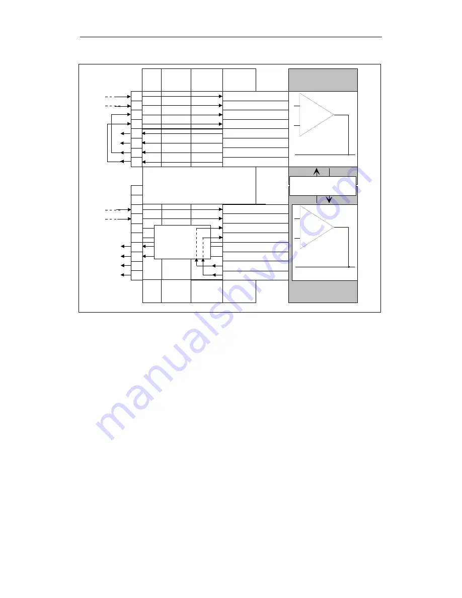
Fig. 3-23
Interconnecting the required SGEs/SGAs (without SPL)
The example is applicable for the 1st axis.
Position values: SN1- = 300 mm, SN1+ = 600 mm
Speed limit values:
Area 1 = 1000 mm/min
Area 2 = 2000 mm/min
Area 3 = 4000 mm/min
Definition of SGEs/SGAs in the NCK monitoring channel
For 840D
Logical slot for the terminal block:
9
Slot number of the submodule with SGEs:
1
Slot number of the submodule with SGAs:
2
I/O number for the signal SN1+:
7
I/O number for the signal SN1-:
6
I/O number for the signal "axis safely referenced":
5
I/O number for the signal "SBH/SG active":
4
I/O number for the signal "SBH/SG de-selection":
2
I/O number for the signal "SBH de-selection":
3
Assumptions for the
example


