11.03
3 Safety-Related Functions
3.11 Encoder mounting arrangements
© Siemens AG 2003 All Rights Reserved
SINUMERIK 840D/SIMODRIVE 611 digital SINUMERIK Safety Integrated (FBSI) - Edition 11.03
3-177
Indexing
mechanism
GEBER_04.DSF
Incremental
encoder
Spindle
Motor
(MSD)
Incremental
encoder
MSD
Belt drive slip
Connection
of motor
encoder
(IMS)
Connection
of direct
position
encoder
(DMS)
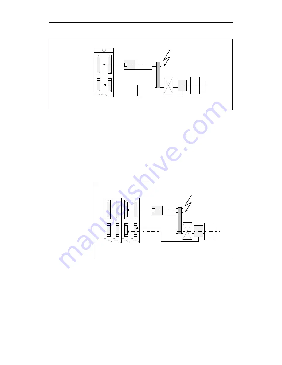
Fig. 3-44
Motor for a drive subject to slip
In the configuration shown in Fig. 3-46 "Configuration of spindle with a drive
subject to slip and two encoders", the SI actual values for the NCK and drive
are derived from one encoder (the motor encoder).
As the actual value of the motor encoder is used for both monitoring channels,
the slip is ignored in this configuration (the same behavior as for 1-encoder
system).
If there is no free actual value input, an additional module must be used.
An actual value input on another drive module must be used for spindle
positioning. This drive may not be an SI axis.
Shift gearbox
GEBER_05.DSF
Incremental encoder
Spindle
Motor
(MSD)
Incremental
encoder
Belt drive slip
Drive
1 2 3 4
1)
1)
2)
2)
Fig. 3-45
Configuration of spindle with a drive subject to slip and 2 encoders
The MD values refer to two cases (refer to Fig. 3-46 "Configuration of spindle
with a drive subject to slip and 2 encoders"):
Configuring options
Machine data for
840D/611 digital


