11.03
7 Configuring example
7.6 SI I/Os using fail-safe modules connected to PROFIBUS DP
© Siemens AG 2003 All Rights Reserved
SINUMERIK 840D/SIMODRIVE 611 digital SINUMERIK Safety Integrated (FBSI) - Edition 11.03
7-425
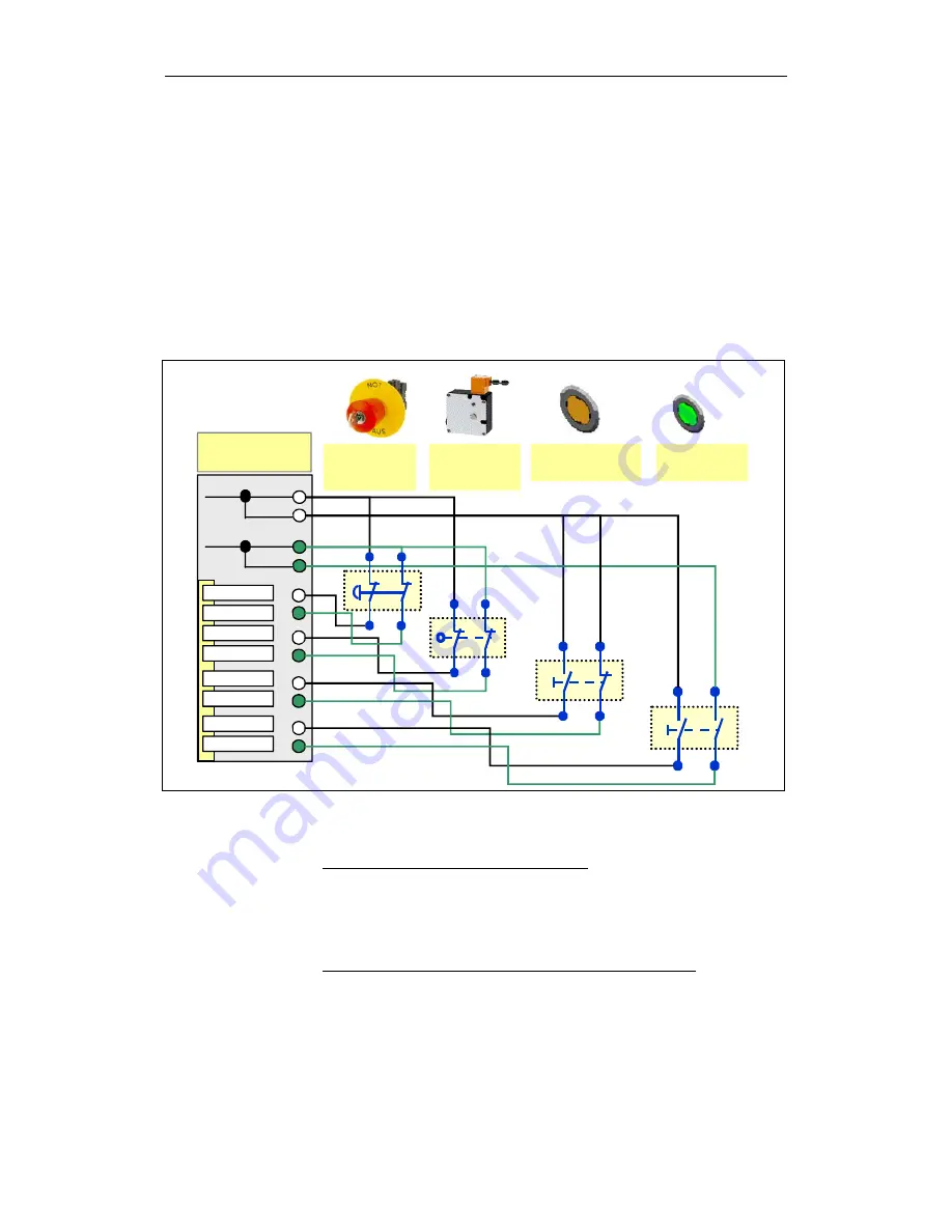
The assignment and significance of the signals for the PROFIsafe modules is
explained below:
The safety-relevant I/O input signals are connected to this module. These are
implemented either using two NC contacts (EMERGENCY Stop button and the
position monitoring function for the protective door) with an exclusive OR
function. This means with one NC contact and one NO contact (agreement
button) - or with two NO contacts (<drive ON> button). As a result of these
versions, in some cases, different parameter settings are obtained in the
hardware configuration under STEP 7.
All of the sensor signals are connected through two channels.
EMERGENCY
stop
Type: NC Contact
1
9
5
13
3
11
7
15
VS1
2; 6
4; 8
VS2
10; 14
12; 16
F-DI
BSP_FDI_Verdrahtung.dsf
Channel 4
Channel 0
Channel 6
Channel 2
Channel 7
Channel 3
Channel 5
Channel 1
Protective
door closed
Type: NC Contact
Enable button
Type: NC/NO contact
Drives ON
Type: NO contact
Fig. 7-31
Example: F-DI connections
Significance and use of the individual signals:
F-DI (channel 0.4) : Emergency Stop actuator
Signal status channel 0 = "1" and channel 4 = "1":
Emergency Stop not pressed
Signal status channel 0 = "0" and channel 4 = "0":
Emergency Stop pressed
F-DI (channel 1.5) : Position monitoring function, protective door
Signal status channel 1 = "1" and channel 5 = "1":
Protective door closed
Signal status channel 1 = "0" and channel 5 = "0":
Protective door not closed
Electronic module 4/8
F-DI DC24V PROFIsafe


