SINAMICS DCM
List Manual (LH8), 02/2015, 6RX1800-0ED76
395
2 Parameters
2.2 List of parameters
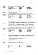
Once the line contactor has dropped out and the "Switch on", "Jog" or "Creep" commands have been sent, in
operating states o4 and o5, the drive waits for voltage at the power unit and for a field current actual value (r52265) >
50% of the field current setpoint (r52268).
If, during this time, no voltage is detected at the power unit and the field current is missing, a message is output
accordingly.
Dependency:
Refer to: p50353
Caution:
The value in p50090 must be smaller than that in p50086 (unless p50086 = 0.0) and p50089!
Note:
This parameter indicates the total wait times during which the drive must pass through operating states o4 and o5
(response threshold for monitoring for the presence of voltage at the power unit, see p50353).
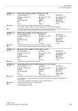
Description:
Sets the line voltage stabilization time.
Caution:
The value in p50090 must be smaller than that in p50086 (unless p50086 = 0.0) and p50089!
Note:
When the "Switch on", "Jog" or "Creep" command is sent and also after a phase failure affecting the line infeed has
been detected with the "Automatic restart" function parameterized (p50086 > 0), the drive waits in operating state o4
for voltage at the power unit.
If amplitude, frequency and phase symmetry remain within the permissible tolerance for longer than this set
stabilization time, line voltage is assumed to be present at the power connections.
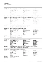
Description:
Sets the thresholds for "Switch on only with low setpoint" and "Automatic pulse inhibit with low setpoint".
Index:
[0] = Switch on only with low setpoint
[1] = Automatic pulse inhibit with low setpoint
Dependency:
Refer to: r52166, r52193
Note:
If p50091[0]:
Switching on is possible only if a setpoint |r52193| < p50091[0] is present at the RFG input.
If a higher setpoint is present, following activation, state o6 will remain set until |r52193| < p50091[0].
If p50091[1]:
If |r52193| and r52166 are smaller than p50091[1], the firing pulses will be inhibited and the motor will switch to state
o2.0.
p50090
Line voltage stabilization time / V_line t_stabil
DC_CTRL
Can be changed:
U, T
Calculated:
-
Access level:
3
Data type:
FloatingPoint32
Dyn. index:
-
Func. diagram:
6950, 6952
P-Group:
-
Unit group:
-
Unit selection:
-
Not for motor type:
-
Scaling:
-
Expert list:
1
Min Max
Factory
setting
0.01 [s]
1.00 [s]
0.05 [s]
p50091[0...1]
Sequence control setpoint threshold / S ctr set thresh
DC_CTRL
Can be changed:
U, T
Calculated:
-
Access level:
2
Data type:
FloatingPoint32
Dyn. index:
-
Func. diagram:
2650, 2651
P-Group:
-
Unit group:
-
Unit selection:
-
Not for motor type:
-
Scaling:
PERCENT
Expert list:
1
Min Max
Factory
setting
0.00 [%]
200.00 [%]
[0] 200.00 [%]
[1] 0.00 [%]
Содержание SINAMICS DCM
Страница 1: ...s SINAMICS SINAMICS DCM List Manual 02 2015 Edition Answers for industry ...
Страница 2: ......
Страница 856: ...3 Function diagrams 3 23 Basic Operator Panel 20 BOP20 SINAMICS DCM 856 List Manual LH8 02 2015 6RX1800 0ED76 ...
Страница 1178: ...4 Faults and alarms 4 2 List of faults and alarms SINAMICS DCM 1178 List Manual LH8 02 2015 6RX1800 0ED76 ...
Страница 1192: ...A Appendix A 2 List of abbreviations SINAMICS DCM 1192 List Manual LH8 02 2015 6RX1800 0ED76 ...
Страница 1202: ...Index SINAMICS DCM 1202 List Manual LH8 02 2015 6RX1800 0ED76 ...
Страница 1203: ......


