SINAMICS DCM
List Manual (LH8), 02/2015, 6RX1800-0ED76
245
2 Parameters
2.2 List of parameters
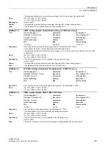
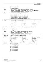
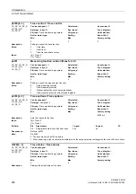
Value:
0:
1x2 wire evaluation
1:
2x2 wire evaluation
2:
3 wire evaluation
3:
4 wire evaluation
Index:
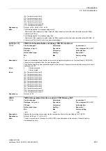
[0] = X531
[1] = X532
[2] = X533
[3] = X534
[4] = X535
[5] = X536
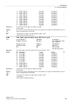
Note:
The temperature sensors are connected to the following terminals:
X531 = channel 0 (for 2x2 wire evaluation, additionally channel 6)
X532 = channel 1 (for 2x2 wire evaluation, additionally channel 7)
X533 = channel 2 (for 2x2 wire evaluation, additionally channel 8)
X534 = channel 3 (for 2x2 wire evaluation, additionally channel 9)
X535 = channel 4 (for 2x2 wire evaluation, additionally channel 10)
X536 = channel 5 (for 2x2 wire evaluation, additionally channel 11)
Re p4108[0...5] = 0, 2, 3 (1x2, 3, 4 wire evaluation):
The temperature channel belonging to the terminal block with the higher number is automatically deactivated (e.g. for
X531 with 3-wire evaluation, channel 6 is deactivated).
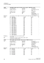
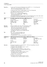
Description:
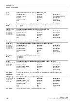
Setting to start the measurement of the wire resistance for a channel for the Terminal Module 150 (TM150).
For a 2 wire evaluation, the total wire resistance is measured and saved. During the temperature evaluation, the
temperature actual value is automatically calibrated using the measured wire resistance.
Procedure:
1. Select the measuring method (1x2/2x2) for the corresponding terminal block (p4108[0...5] = 0, 1).
2. Set the required sensor type for the corresponding channel (p4100[x] = 1 ... 6, x = 0...5 or 0...11).
3. Jumper the sensor to be connected (short-circuit the sensor conductor close to the sensor).
4. Connect the sensor conductors to the appropriate terminals 1(+), 2(-) or 3(+), 4(-).
5. For the corresponding channel, start the measurement of the wire resistance (p4109[x] = 1).
6. After p4109[x] = 0, check the measured resistance value in p4110[x].
7. Remove the jumper across the temperature sensor.
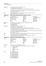
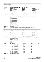
Value:
0:
Inactive
1:
Start
Index:
[0] = Temperature channel 0
[1] = Temperature channel 1
[2] = Temperature channel 2
[3] = Temperature channel 3
[4] = Temperature channel 4
[5] = Temperature channel 5
[6] = Temperature channel 6
[7] = Temperature channel 7
[8] = Temperature channel 8
[9] = Temperature channel 9
[10] = Temperature channel 10
[11] = Temperature channel 11
Dependency:
Refer to: p4100, p4108, p4110
Notice:
Wire resistance measurement is only possible for 1x2 or 2x2 wire evaluation (p4108[0...5] = 0, 1).
Note:
The wire resistance value can be also directly entered into p4110[0...11].
The automatic conductor calibration for 1x2 and 2x2 wire evaluation is always performed with the value in
p4110[0...11].
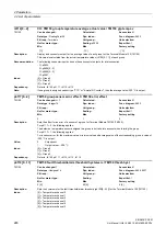
p4109[0...11]
TM150 wire resistance measurement / TM150 R_wire meas
TM150
Can be changed:
T
Calculated:
-
Access level:
1
Data type:
Integer16
Dyn. index:
-
Func. diagram:
9626, 9627
P-Group:
-
Unit group:
-
Unit selection:
-
Not for motor type:
-
Scaling:
-
Expert list:
1
Min Max
Factory
setting
0 1
0
Содержание SINAMICS DCM
Страница 1: ...s SINAMICS SINAMICS DCM List Manual 02 2015 Edition Answers for industry ...
Страница 2: ......
Страница 856: ...3 Function diagrams 3 23 Basic Operator Panel 20 BOP20 SINAMICS DCM 856 List Manual LH8 02 2015 6RX1800 0ED76 ...
Страница 1178: ...4 Faults and alarms 4 2 List of faults and alarms SINAMICS DCM 1178 List Manual LH8 02 2015 6RX1800 0ED76 ...
Страница 1192: ...A Appendix A 2 List of abbreviations SINAMICS DCM 1192 List Manual LH8 02 2015 6RX1800 0ED76 ...
Страница 1202: ...Index SINAMICS DCM 1202 List Manual LH8 02 2015 6RX1800 0ED76 ...
Страница 1203: ......

