2 Parameters
2.2 List of parameters
SINAMICS DCM
366
List Manual (LH8), 02/2015, 6RX1800-0ED76
Description:
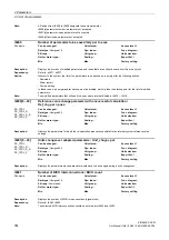
Display and binector output for a delay after POWER ON.
After power-on, binector output r9935.0 is set with the start of the first sampling time and is again reset after approx.
100 ms.
Description:
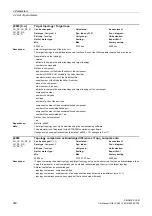
Displays the error counter for the individual DRIVE-CLiQ connections/cables.
r9936[0]: sum of the error counter for all connections
r9936[1]: not used
r9936[2]: error counter for the feeder cable to DRIVE-CLiQ components with component number 2
...
r9936[199]: error counter for the feeder cable to DRIVE-CLiQ components with component number 199
The feeder cable is the DRIVE-CLiQ cable that is connected to a component in the direction of the Control Unit.
Dependency:
Refer to: p9937, p9938
Description:
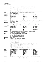
Sets the configuration for the DRIVE-CLiQ diagnostics (error counter r9936).
Using this function, connections and cables of DRIVE-CLiQ connections can be checked for transfer errors. The error
counter is evaluated in the PHY blocks involved.
Dependency:
Refer to: r9936, p9938
Note:
Re bit 00:
To activate this function, p9938 must be set to 0 (inactive).
After changing the error counter (r9936), an appropriate alarm is output.
The alarm automatically disappears after 5 seconds.
Re bit 08:
With p9937.8 = 1, the error counters are reset (r9936[0...199]).
After the reset, p9937.8 is automatically set to 0.
r9935.0
BO: POWER ON delay signal / POWER ON t_delay
CU_DC, CU_DC_R,
CU_DC_R_S,
CU_DC_S
Can be changed:
-
Calculated:
-
Access level:
3
Data type:
Unsigned8
Dyn. index:
-
Func. diagram:
-
P-Group:
-
Unit group:
-
Unit selection:
-
Not for motor type:
-
Scaling:
-
Expert list:
1
Min Max
Factory
setting
- -
-
Bit field:
Bit
Signal name
1 signal
0 signal
FP
00
POWER ON delay signal
High
Low
-
r9936[0...199]
DRIVE-CLiQ diagnostic error counter connection / DQdiag err counter
CU_DC, CU_DC_R,
CU_DC_R_S,
CU_DC_S
Can be changed:
-
Calculated:
-
Access level:
4
Data type:
Integer32
Dyn. index:
-
Func. diagram:
-
P-Group:
-
Unit group:
-
Unit selection:
-
Not for motor type:
-
Scaling:
-
Expert list:
1
Min Max
Factory
setting
- -
-
p9937
DRIVE-CLiQ diagnostic configuration / DQ diag config
CU_DC, CU_DC_R,
CU_DC_R_S,
CU_DC_S
Can be changed:
U, T
Calculated:
-
Access level:
4
Data type:
Unsigned16
Dyn. index:
-
Func. diagram:
-
P-Group:
-
Unit group:
-
Unit selection:
-
Not for motor type:
-
Scaling:
-
Expert list:
1
Min Max
Factory
setting
-
-
0000 0000 0000 0000 bin
Bit field:
Bit
Signal name
1 signal
0 signal
FP
00
Alarm for connection error
Yes
No
-
08
Reset error counter
Yes
No
-
Содержание SINAMICS DCM
Страница 1: ...s SINAMICS SINAMICS DCM List Manual 02 2015 Edition Answers for industry ...
Страница 2: ......
Страница 856: ...3 Function diagrams 3 23 Basic Operator Panel 20 BOP20 SINAMICS DCM 856 List Manual LH8 02 2015 6RX1800 0ED76 ...
Страница 1178: ...4 Faults and alarms 4 2 List of faults and alarms SINAMICS DCM 1178 List Manual LH8 02 2015 6RX1800 0ED76 ...
Страница 1192: ...A Appendix A 2 List of abbreviations SINAMICS DCM 1192 List Manual LH8 02 2015 6RX1800 0ED76 ...
Страница 1202: ...Index SINAMICS DCM 1202 List Manual LH8 02 2015 6RX1800 0ED76 ...
Страница 1203: ......


