14
Laser Scanners
RF627, RF627Smart [Revision 2.1.2] 20.09.2021
12.2. First connection
·
Perform the network configuration in accordance with the previous paragraph.
·
Connect the scanner to the PC or to the network switch.
·
Connect the power supply (9...30V) to the scanner (cable #2, a red wire is "plus"
of the power supply, a brown wire is "minus").
Within 8 seconds after powering on, the FPGA firmware is booting and the Ethernet
interface is initializing (the red LED blinks).
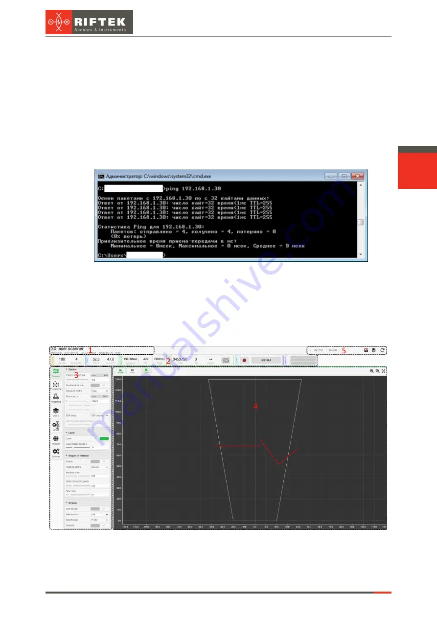
Next, it is recommended to check the connection using the console command "ping
192.168.1.30 (or the current IP address of the scanner)". If all the settings are correct, the
scanner will respond to the command. A typical result is shown below:
The scanner is ready to operate.
To turn off the scanner, turn off the power supply.
13. Web page
The web page is intended to check the operation and configure parameters of the
scanner. To access the web page, enter the IP address of the scanner into the address bar
of the web browser:
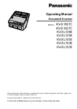
The web page is divided into five areas:
1. Scanner name, scanner model, serial number, firmware version and measuring
ranges.
2. Scanner status indicators.
Содержание RF627 Series
Страница 1: ...Certified according to ISO 9001 2015 LASER SCANNERS User s manual RF627 Series RF627Smart Series...
Страница 9: ...RF627 RF627Smart Revision 2 1 2 20 09 2021 Laser Scanners 9 Figure 2 Figure 3...
Страница 50: ...50 Laser Scanners RF627 RF627Smart Revision 2 1 2 20 09 2021...
Страница 97: ...RF627 RF627Smart Revision 2 1 2 20 09 2021 Laser Scanners 97...


